Rev. 1.0, 02/00, page 355 of 1141
17.3
Operation
17.3.1
Watchdog Timer Operation
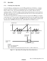
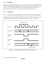
To use the WDT as a watchdog timer, set the WT/
,7
and TME bits in WTCSR to 1. Software
must prevent WTCNT overflows by rewriting the WTCNT value (normally by writing H'00)
before overflow occurs. This ensures that WTCNT does not overflow while the system is
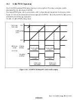
operating normally. If WTCNT overflows without being rewritten because of a system crash or
other error, the chip is reset, or an NMI interrupt is generated, for 518 system clock periods (518
φ
). This is illustrated in figure 17.3.
An internal reset request from the watchdog timer and reset input from the
5(6
pin are handled
via the same vector. The reset source can be identified from the value of the XRST bit in SYSCR.
If a reset caused by an input signal from the
5(6
pin and a reset caused by WDT overflow occur
simultaneously, the
5(6
pin reset has priority, and the XRST bit in SYSCR is set to 1.
WTCNT value
H'00
Time
H'FF
WT/ =1
TME=1
H'00 written
to WTCNT
WT/ =1
TME=1
H'00 written
to WTCNT
518 system clock period
Internal reset
signal
WT/
TME
[Legend]
Overflow
Internal reset
generated
OVF=1*
: Timer mode select bit
: Timer enable bit
Note: * Cleared to 0 by an internal reset when OVF is set to 1. XRST is cleared to 0.
Figure 17.3 Operation in Watchdog Timer Mode (when Reset)


