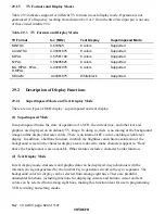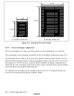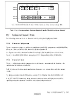
Rev. 1.0, 02/00, page 823 of 1141
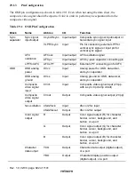
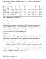
Block
Name
Abbrev.
I/O
Function
Data
slicer
Composite
video signal
Cvin2
Input
Composite video signal input (2 Vpp,
with a sync tip clamp circuit)
29.1.4
Register Configuration
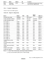
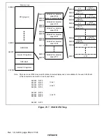
Table 29.2 shows the OSD registers.
Table 29.2
Register Configuration
Name
Abbrev.
R/W
Size
Initial
Value
Address
*
1
Character data ROM
OSDROM
—
24576 bytes
—
H'040000
Display data RAM (Master)
OSDRAM
R/W
768 bytes
Undefined
H'D800
Display data RAM (Slave)
—
768 bytes
Undefined
—
Row register 1
CLINE1
R/W
Byte
H'00
H'D200
Row register 2
CLINE2
R/W
Byte
H'00
H'D201
Row register 3
CLINE3
R/W
Byte
H'00
H'D202
Row register 4
CLINE4
R/W
Byte
H'00
H'D203
Row register 5
CLINE5
R/W
Byte
H'00
H'D204
Row register 6
CLINE6
R/W
Byte
H'00
H'D205
Row register 7
CLINE7
R/W
Byte
H'00
H'D206
Row register 8
CLINE8
R/W
Byte
H'00
H'D207
Row register 9
CLINE9
R/W
Byte
H'00
H'D208
Row register 10
CLINE10
R/W
Byte
H'00
H'D209
Row register 11
CLINE11
R/W
Byte
H'00
H'D20A
Row register 12
CLINE12
R/W
Byte
H'00
H'D20B
Vertical display position
register
VPOS
R/W
Word
H'F000
H'D20C
Horizontal display position
register
HPOS
R/W
Byte
H'00
H'D20E
Digital output specification
register
DOUT
R/W
Byte
H'02
H'D20F
Screen control register
DCNTL
R/W
Word
H'0000
H'D210
OSD format register
DFORM
R/(W)
*
2
Word
H'00F8
H'D212
Notes: 1. Lower 16 bits of the address. (excluding character data ROM)
2. Only 0 can be written to bits 8 and 0 to clear the flags.


