Rev. 1.0, 02/00, page 864 of 1141
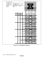
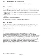
Horizontal display position
Display block
Character display
position
Blank character
Row 1
YBO
1 2 3 4 5 6 7
29
32
.......................................................................
.....
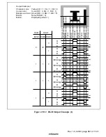
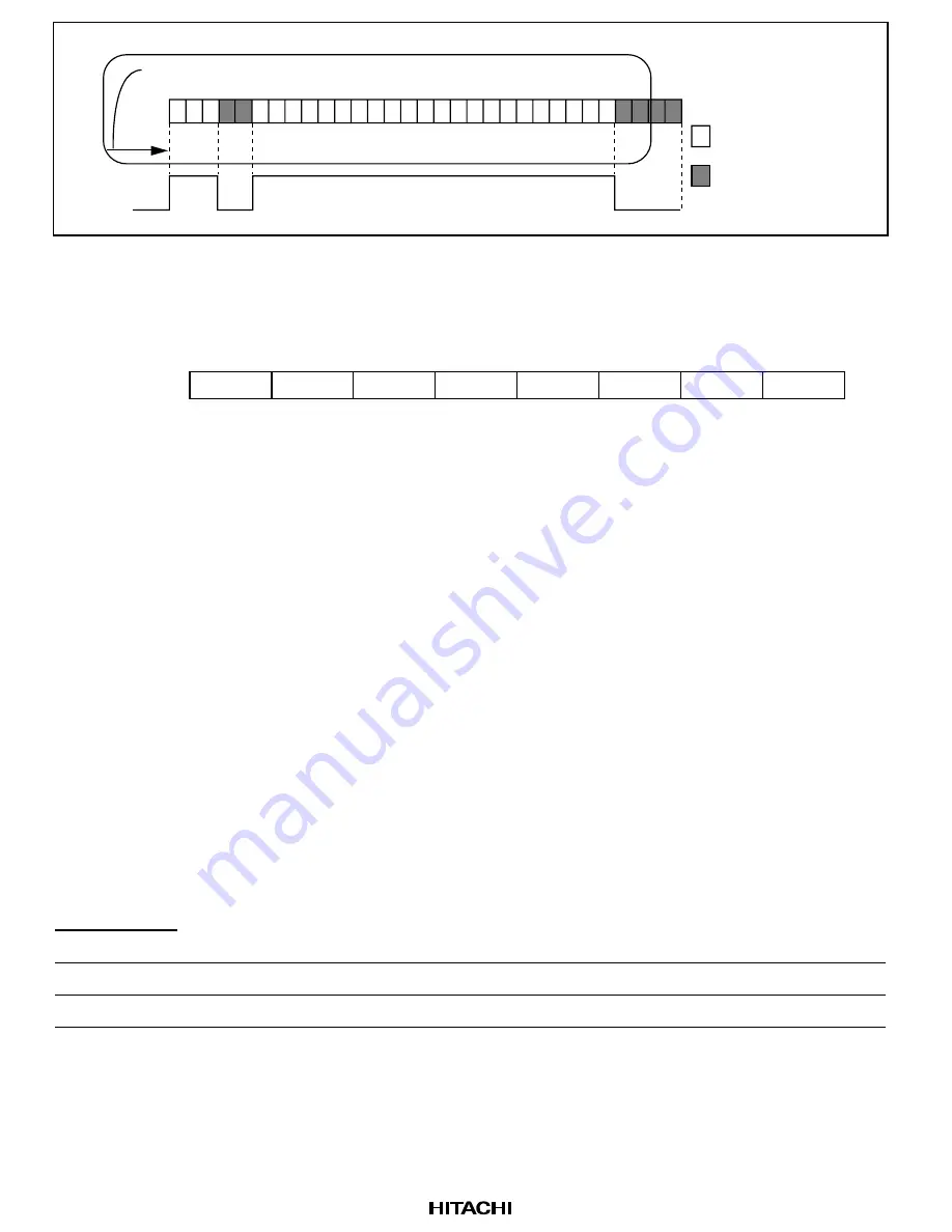
Figure 29.15 YBO Output Example
29.7.3
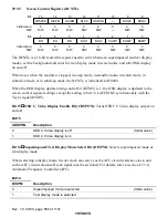
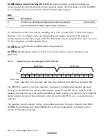
Digital Output Specification Register (DOUT)
0
1
—
2
R/W
3
4
R/W
R/W
5
7
DOBC
0
DSEL
0
CRSEL
0
—
1
—
0
—
—
0
—
R/W
R/W
RGBC
0
YCOC
0
6
Bit:
Initial value:
R/W:
The DOUT is used to choose settings for digital output.
The DOUT is an 8-bit read/write register. When reset, when the module is stopped, in sleep mode,
in standby mode, in watch mode, in subactive mode, or in subsleep mode, it is initialized to H'02.
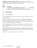
When the OSD display update timing control bit is 1, the OSD display is updated to the RGBC,
YCOC and DOBC bit settings synchronously with the Vsync signal (OSDV).
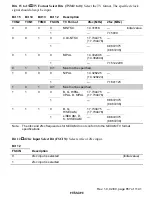
The R, G, B, YCO, and YBO outputs are multiplexed with port 8 inputs/outputs. For details on pin
function selection, refer to section 10.9, Port 8.
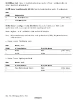
Bit 7
Reserved: Always read as 0. When 1 is written to this bit, correct operation is not
guaranteed.
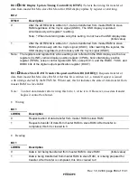
Bit 6
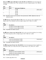
R, G, B Digital Output Specification Bit (RGBC): Specifies the R, G, B digital output
format.
Bit 6
RGBC
Description
0
Character output is specified
(Initial value)
1
Combined character, border, cursor, background, and button output is specified

