Rev. 1.0, 02/00, page 362 of 1141
18.1.3
Pin Configuration
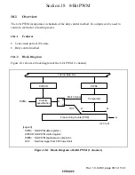
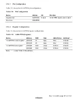
Table 18.1 shows the 8-bit PWM pin configuration.
Table 18.1
Pin Configuration
Name
Abbrev.
I/O
Function
8-bit PWM square-wave output pin 0
PWM0
Output
8-bit PWM square-wave output 0
8-bit PWM square-wave output pin 1
PWM1
Output
8-bit PWM square-wave output 1
8-bit PWM square-wave output pin 2
PWM2
Output
8-bit PWM square-wave output 2
8-bit PWM square-wave output pin 3
PWM3
Output
8-bit PWM square-wave output 3
18.1.4
Register Configuration
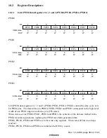
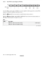
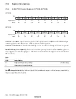
Table 18.2 shows the 8-bit PWM register configuration.
Table 18.2
8-Bit PWM Registers
Name
Abbrev.
R/W
Size
Initial Value
Address*
8-bit PWM data register 0
PWR0
W
Byte
H'00
H'D126
8-bit PWM data register 1
PWR1
W
Byte
H'00
H'D127
8-bit PWM data register 2
PWR2
W
Byte
H'00
H'D128
8-bit PWM data register 3
PWR3
W
Byte
H'00
H'D129
8-bit PWM control register
PW8CR
R/W
Byte
H'F0
H'D12A
Port mode register 3
PMR3
R/W
Byte
H'00
H'FFD0
Note:
*
Lower 16 bits of the address.


