Rev. 1.0, 02/00, page 606 of 1141
26.4.6
Operation
5-Bit DFG Counter: The 5-bit DFG counter increments the count at the DFG edges selected by
the EDG bit of HSW Mode Register 2. The DFG counter is cleared by a DPG rising edge, or by
writing to the CCLR bit of the DFG reference register 1.
16-Bit Timer Counter: The 16-bit timer counter can operate in DFG reference mode or in free-
running mode.
•
DFG Reference Mode
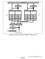
The timer counter operates by referencing the DFG signal. When the 5-bit DFG counter value
matches the value specified in the DFG reference register 1 or 2, the 16-bit timer counter is
initialized; this is the start point of the FIFO output timing.
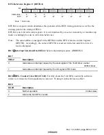
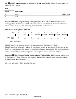
In DFG reference mode, the start point specifying method can be selected by the FGR2OFF bit
of the HSW mode register 2: one way is to specify both FIFO1 and FIFO2 by only one register
(DFG reference register 1), and the other is to specify FIFO1 and FIFO2 by DFG reference
registers 1 and 2, respectively. When only the DFG reference register 1 is used, the continuous
values must be set to FIFO1 and FIFO2 as the timing patters.
•
Free-Running Mode
The timer counter operates in association with the prescaler unit. When the 18-bit free-running
counter in the prescaler unit overflows, the 16-bit timer counter in the HSW timing generator
is initialized; this is the start point of the FIFO output timing.
Compare Circuit: The compare circuit compares the 16-bit timer counter value with the FIFO
timing pattern, and when they match, the compare circuit generates a trigger signal for outputting
the next-stage FIFO data.
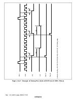
FIFO: The FIFO generates a head switch signal for VCR and patterns for servo control. Data is
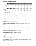
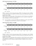
set to FIFO by using the FIFO timing pattern registers 1 and 2, and FIFO output pattern registers 1
and 2.
The FIFO operates in single mode and loop mode. In these two modes, the number of output
stages can be selected by the FIFO output group selection bit: 20-stage output using both FIFO1
and FIFO2 or 10-stage output using only FIFO1.
•
Single Mode
The output pattern data is output when the timing pattern matches the counter value. The data,
once output, is lost, and the internal pointer is decrementd by 1. After the last data is output,
the FIFO stops operation until data is written again. When 20-stage output is used, writing in
FIFO1 and FIFO2 must be controlled by software.

