Rev. 1.0, 02/00, page 804 of 1141
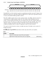
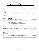
Bit 15
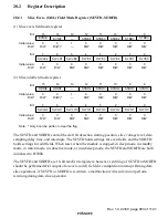
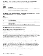
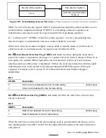
Even- (Odd-) Field Slice Completion Interrupt Enable Flag (EVNIE, ODDIE):
Enables or disables the generation of even- (odd-) field slice completion interrupts.
Bit 15
EVNIE
ODDIE
Description
0
Disables even- (odd-) field slice completion interrupt
(Initial value)
1
Enables even- (odd-) field slice completion interrupt
Bit 14
Even- (Odd-) Field Slice Interrupt Completion Flag (EVNIF, ODDIF): Set when data
slicing for all specified lines of even (odd) field is completed.
Bit 14
EVNIF
ODDIF
Description
0
[Clearing condition]
When 0 is written after reading 1
(Initial value)
1
[Setting condition]
When data slicing is completed for all specified lines of even (odd) field
Bit 13
Reserved: Cannot be modified and is always read as 1.
Bits 12 to 8
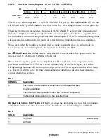
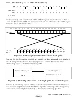
Start Bit Detection Starting Position Bits:
(STBE4 to STBE0) (STBO4 to STBO0): Set the starting position for start bit detection in even
(odd) fields.
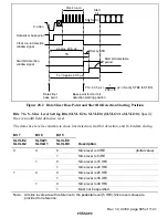
The base point for the data slicer is the falling edge of the horizontal sync signal (slicer base point
H) synchronized within the LSI; the starting position for start bit detection can be set using STBE4
to STBE 0 (STBO4 to STBO0) in 288
×
fh (where fh is the horizontal sync signal frequency)
clock units from approximately 23.5
µ
s after the data slicer base point.
The start bit detection end position is at approximately 29.5
µ
s after the data slicer base point.
In start bit detection, the presence of the rising edge of start bits in the interval between these
starting and ending positions is detected. Further, the start bit detection window signal, which
becomes the base point for the start bit detection starting position, can be adjusted by means of the
data slicer detection window register of the sync separator. For details, refer to section 27.2.10,
Data Slicer Detection Window Register (DDETWR).
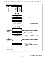
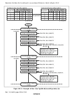
Figure 28.2 shows the data slicer base point and start bit detection starting position.


