Rev. 1.0, 02/00, page 294 of 1141
Bit 0
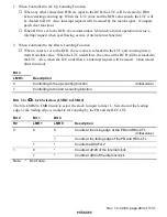
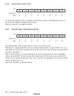
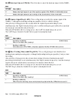
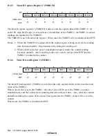
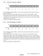
Capture Signals of the TMRU-1 (CPS): In combination with the LAT bit (Bit 7) of the
TMR2, this bit works to select the capture signals of the TMRU-1. This bit becomes valid when
the LAT bit is being set to 1. It will also become valid when the RLD/CAP bit (Bit 1) is being set
to 1. Nonetheless, it will be invalid when the RLD/CAP bit (Bit 1) is being set to 0.
Bit 0
CPS
Description
0
Capture signals at the rising edge of the CFG
(Initial value)
1
Capture signals at the edge of the IRQ3
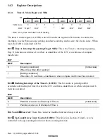
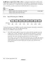
15.2.2
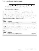
Timer R Mode Register 2 (TMRM2)
0
0
1
0
R/(W)*
2
0
R/W
3
0
4
0
R/W
5
0
6
0
7
R/(W)*
R/W
R/W
PS10
R/W
PS11
0
R/W
LAT
PS31
PS30
CP/SLM
CAPF
SLW
Bit :
Initial value :
R/W :
The timer R mode register 2 (TMRM2) is an 8-bit read/write register which works to identify the
operation mode and to control the slow tracking processing.
When reset, the TMRM2 is initialized to H'00.
Note: *
The CAPF bit and the SLW bit, respectively, works to latch the interrupt causes and
writing 0 only is valid. Consequently, when these bits are being set to 1, respective
interrupt requests will not be issued. Therefore, it is necessary to check these bits
during the course of the interrupt processing routine to have them cleared.
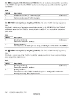
Also, priority is given to the set and, when an interrupt cause occur while the a clearing
command (BCLR, MOV, etc.) is being executed, the CAPF bit and the SLW bit will
not be cleared respectively and it thus becomes necessary to pay attention to the
clearing timing.

