Rev. 1.0, 02/00, page 69 of 1141
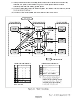
4. In the power-down mode, the analog section of the servo circuits are not turned off,
therefore Vcc (Servo) current does not go low. When power-down is needed,
externally shut down the analog system power.
*
1 The SCI1 status differs from the internal register. For details, refer to section 22, Serial
Communication Interface 1.
*
2 The state of the 12-bit PWM is the same as that of the servo circuit.
Program-halted state
Conditions for mode transition (1)
Conditions for mode transition (2)
Interruption factor
Sleep
(high-speed)
mode
Sleep
(medium-speed)
mode
Subsleep
mode
Program execution state
Reset state
Flag
SLEEP
instruction
Interrupt
LSON SSBY TMA3 DTON
a
0
1
0
*
b
*
1
1
0
c
0
1
1
1
d
1
1
1
1
e
0
0
*
*
f
1
0
1
*
g
SCK1 to 0 = 0
h
SCK1 to 0 0 (either 1 bit = 0)
Power-down mode
Active
(high-speed)
mode
Active
(medium-speed)
mode
Subactive
mode
Program-halted state
Watch
mode
Standby
mode
IRQ0
to
1
IRQ0
to
1, Timer A interruption
All interruption (excluding servo system)
IRQ0
to
5, Timer A interruption
1
2
3
4
Interrupt
Interrupt
SLEEP
instruction
SLEEP
instruction
e
Note: When a transition is made between
modes by means of an interrupt,
transition cannot be made on interrupt
source generation alone. Ensure that
interrupt handling is performed after
accepting the interrupt request
SLEEP
instruction a
1
Interrupt
1
2
SLEEP
instruction
SLEEP
instruction
SLEEP
instruction
SLEEP
instruction
a
b
g
h
d
SLEEP
instruction
c
e
3
Interrupt 2
Interrupt 3
Interrupt 2
Interrupt 4
c
SLEEP
instruction
d
b
b
SLEEP
instruction
SLEEP
instruction 1
Note:
*
Don't care
Figure 4.1 Mode Transitions

