Rev. 1.0, 02/00, page 913 of 1141
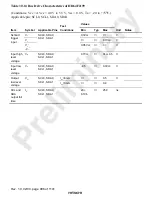
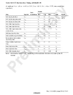
Table 30.18 I
2
C Bus Interface Timing of HD64F2199
(Conditions: Vcc = AVcc = 4.0 V to 5.5 V, Vss = 0.0 V, Ta = –20 to +75
°
C unless otherwise
specified.)
Values
Item
Symbol
Test
Conditions
Min
Typ
Max
Unit
Figure
SCL input cycle time
t
SCL
12
t
cyc
SCL input high pulse width
t
SCLH
3
t
cyc
SCL input low pulse width
t
SCLL
5
t
cyc
SCL, SDA input rise time
t
sr
7.5
*
t
cyc
SCL, SDA input fall time
t
sf
300
ns
SCL, SDA input spike pulse
removal time
t
sp
1
t
cyc
SDA input bus free time
t
BUF
5
t
cyc
Start condition input hold time
t
STAS
3
t
cyc
Re-transmit start condition
input setup time
t
STAH
3
t
cyc
Stop condition input setup
time
t
STOS
3
t
cyc
Data input setup time
t
SDAS
0.5
t
cyc
Data input hold time
t
SDAH
0
ns
SCL, SDA capacity load
C
b
400
pF
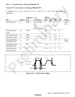
Figure
30.18
Note:
Can also be set to 17.5 t
cyc
depending on the selection of clock to be used by the I
2
C
module.


