Rev. 1.0, 02/00, page 63 of 1141
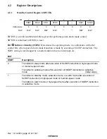
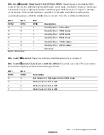
Bits 5 and 4
Interrupt control modes 1 and 0 (INTM1, INTM0)
These bits are for selecting the interrupt control mode of the interrupt controller. For details of the
interrupt control modes, see section 6.4.1, Interrupt Control Modes and Interrupt Operation.
Bit 5
Bit 4
INTM1
INTM0
Interrupt
Control Mode
Description
0
0
Interrupt is controlled by bit I
(Initial value)
0
1
1
Interrupt is controlled by bits I and UI, and ICR
0
Cannot be used in this LSI
1
1
Cannot be used in this LSI
Bit 3
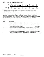
External Reset (XRST): Indicates the reset source. When the watchdog timer is used, a
reset can be generated by watchdog timer overflow as well as by external reset input. XRST is a
read-only bit. It is set to 1 by an external reset and cleared to 0 by watchdog timer overflow.
Bit 3
XRST
Description
0
A reset is generated by watchdog timer overflow
1
A reset is generated by an external reset
(Initial value)
Bits 2 and 1
Reserved: These bits cannot be modified and are always read as 0.
Bit 0
Reserved: This bit is always read as 1.
3.3
Operating Mode (Mode 1)
The CPU can access a 16 Mbyte address space in advanced mode.


