Rev. 1.0, 02/00, page 334 of 1141
16.3.2
Counting Timing of the FRC
The FRC is counted up by the inputting clock. By setting the CKS1 and CKS0 of the TCRX, the
inputting clock can be selected from among three different types of clocks (
φ
/4,
φ
/16 and
φ
/64)
and the DVCFG.
•
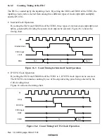
Internal Clock Operation
By setting the CKS1 and CKS0 bits of the TCRX, three types of internal clocks (
φ
/4,
φ
/16 and
φ
/64), generated by dividing the system clock (
φ
) can be selected. Figure 16.3 shows the
timing chart.
FRC
Internal clock
φ
FRC input
clock
N
N-1
N+1
Figure 16.3 Count Timing for Internal Clock Operation
•
DVCFG Clock Operation
By setting the CKS1 and CKS0 bits of the TCRX to 1, DVCFG clock input can be selected.
The DVCFG clock makes counting by use of the edge detecting pulse being selected by the
CFG dividing timer.
Figure 16.4 shows the timing chart.
FRC
CFG
FRC input
clock
φ
N
N+1
DVCFG
Figure 16.4 Count Timing for CFG Clock Operation


