Rev. 1.0, 02/00, page 47 of 1141
2.7
Addressing Modes and Effective Address Calculation
2.7.1
Addressing Mode
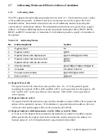
The CPU supports the eight addressing modes listed in table 2.11. Each instruction uses a subset
of these addressing modes. Arithmetic and logic instructions can use the register direct and
immediate modes. Data transfer instructions can use all addressing modes except program-
counter relative and memory indirect. Bit-manipulation instructions use register direct, register
indirect, or absolute addressing mode to specify an operand, and register direct (BSET, BCLR,
BNOT, and BTST instructions) or immediate (3-bit) addressing mode to specify a bit number in
the operand.
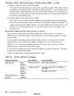
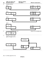
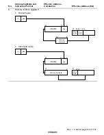
Table 2.11
Addressing Modes
No.
Addressing Mode
Symbol
1
Register direct
Rn
2
Register indirect
@ERn
3
Register indirect with displacement
@(d:16,ERn)/@(d:32,ERn)
4
Register indirect with post-increment
Register indirect with pre-decrement
@ERn+
@-ERn
5
Absolute address
@aa:8/#@aa:16/@aa:24/@aa:32
6
Immediate
#xx:8/#xx:16/#xx:32
7
Program-counter relative
@(d:8,PC)/@(d:16,PC)
8
Memory indirect
@@aa:8
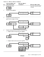
(1) Register Direct–Rn
The register field of the instruction code specifies an 8-, 16-, or 32-bit general register
containing the operand. R0H to R7H and R0L to R7L can be specified as 8-bit registers. R0
to R7 and E0 to E7 can be specified as 16-bit registers. ER0 to ER7 can be specified as
32-bit registers.
(2) Register Indirect–@Ern
The register field of the instruction code specifies an address register (ERn) which contains the
address of the operand in memory. If the address is a program instruction address, the lower
24 bits are valid and the upper 8 bits are all assumed to be 0 (H'00).
(3) Register Indirect with Displacement–@(d:16, ERn) or @(d:32, ERn)
A 16-bit or 32-bit displacement contained in the instruction is added to an address register
(ERn) specified by the register field of the instruction, and the sum gives the address of a
memory operand. A 16-bit displacement is sign-extended when added.


