Rev. 1.0, 02/00, page 310 of 1141
15.5.2
Reeling Controls
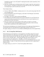
CFG counts can be captured by making 16-bit capturing operation combining the TMRU-1 and
TMRU-2. By choosing the IRQ3 as the capture signal, and by counting the CFG within the
duration of the reel pulse being input through the
,54
6
pin, reeling controls, etc. can be effected.
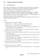
Settings
•
Setting P13/
,54
6
pin as the
,54
6
pin
Set the PMR13 bit (bit 3) of the port mode register 1 (PMR1) to 1. See section 10.3.2, Port
Mode Register (PMR1).
•
Setting the timer R mode register 1 (TMRM1)
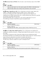
CLR2 bit (bit 7) = 1: Works to clear after making the TMRU-2 capture.
PS21 and PS20 (bits 3 and 2) = (0 and 0): The underflowing signals of the TMRU-1 are to
be used as the clock source for the TMRU-2.
RLD/CAP bit (bit 1) = 1: The TMRU-1 has been set to make the capturing operation.
CPS bit (bit 0) = 1: The edge of the IRQ3 signal is to be used as the capture signal for the
TMRU-1 and TMRU-2.
•
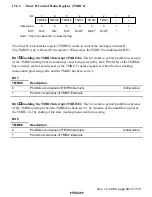
Setting the timer R mode register 2 (TMRM2)
LAT bit (bit 7) = 1: The edge of the IRQ3 signal is to be used as the capture signal for the
TMRU-1 and TMRU-2.
PS11 and PS10 (bits 6 and 5) = (0 and 0): The rising edge of the CFG signal is to be used
as the clock source for the TMRU-1.
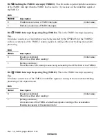
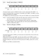
CP/SLM bit (bit 2) = 0: The capture signal is to work to issue the TMRI3 interrupt request.
15.5.3
Slow Tracking Mono-Multi Function
When performing slow reproductions or still reproductions, the braking timing for the capstan
motor is determined by use of the edge of the DVCTL signal. The slow tracking mono-multi
function works to measure the time from the leading edge of the DVCTL signal down to the
desired point to issue the interrupt request. In actual programming, this interrupt should be used to
activate the brake of the capstan motor. The TMRU-3 should be used to perform time
measurements for the slow tracking mono-multi function. Also, the braking process can be made
using the TMRU-2.

