Rev. 1.0, 02/00, page 611 of 1141
•
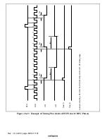
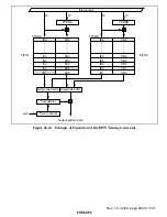
Example of the operation in loop mode mode
1
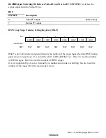
Set the number of loop stages in HSLP register (e.g. HSLP = H'44)
2
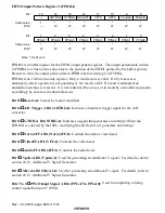
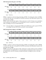
Write the output pattern data (PA0) to FPDRA.
3
Write the output timing (t
A1
) to FTPRA. t
A1
is written in FIFO1 together with PA0. This
initializes the output pattern data to PA0.
4
Repeat the steps in the same way, until PA1, PA2, etc., are set.
5
Write the output pattern data (PB0) to FPDRB.
6
Write the output timing (t
B1
) to FTPRB. t
B1
is written in FIFO2 together with PB0. This
initializes the output pattern data to PB0.
7
Repeat the steps in the same way, until PB1, PB2, etc., are set.
By step 3, the pattern data PA0 is output.
If t
A1
matches the timer counter, the pattern data PA1 is output.
If t
A2
matches the timer counter, the pattern data PA2 is output.
.
.
.
If t
A4
matches the timer counter, the pattern data PA4 is output.
If t
A5
matches the timer counter, the pattern data PB0 is output.
If t
B1
matches the timer counter, the pattern data PB1 is output.
.
.
.
If t
B4
matches the timer counter, the pattern data PB4 is output.
If t
B5
matches the timer counter, the pattern data PA0 is output.
.
.
.

