


Rev. 1.0, 02/00, page 192 of 1141
10.3
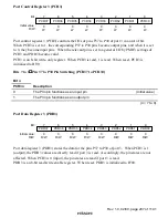
Port 1
10.3.1
Overview
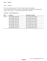
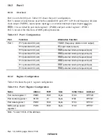
Port 1 is an 8-bit I/O port. Table 10.5 shows the port 1 configuration.
Port 1 consists of pins that are used both as standard I/O ports (P17 to P10) and frequency division
clock output (TMOW), input capture input (
,&
), or external interrupt request inputs (
,54
8
to
,54
3
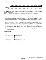
). It is switched by port mode register 1 (PMR1) and port control register 1 (PCR1).
Port 1 can select the functions of MOS pull-up transistors.
Table 10.5
Port 1 Configuration
Port
Function
Alternative Function
P17 (standard I/O port)
TMOW (frequency division clock output)
P16 (standard I/O port)
,&
(input capture input)
P15 (standard I/O port)
,54
8
(external interrupt request input)
P14 (standard I/O port)
,54
7
(external interrupt request input)
P13 (standard I/O port)
,54
6
(external interrupt request input)
P12 (standard I/O port)
,54
5
(external interrupt request input)
P11 (standard I/O port)
,54
4
(external interrupt request input)
Port 1
P10 (standard I/O port)
,54
3
(external interrupt request input)
10.3.2
Register Configuration
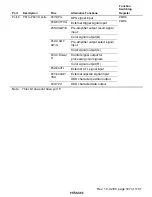
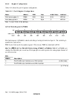
Table 10.6 shows the port 1 register configuration.
Table 10.6
Port 1 Register Configuration
Name
Abbrev.
R/W
Size
Initial Value
Address
*
Port mode register 1
PMR1
R/W
Byte
H'00
H'FFCE
Port control register 1
PCR1
W
Byte
H'00
H'FFD1
Port data register 1
PDR1
R/W
Byte
H'00
H'FFC1
MOS pull-up select
register 1
PUR1
R/W
Byte
H'00
H'FFE1
Note:
*
Lower 16 bits of the address.