Rev. 1.0, 02/00, page 564 of 1141
Bit 4
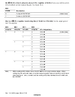
SW Bit of the Feedback Section of CTL Amplifier (CTLFB): Turns on or off the switch
of the feedback section to adjust the gain. See figure 26.4.
Bit 4
CTLFB
Description
0
Turns off CTLFB SW
(Initial value)
1
Turns on CTLFB SW
Bits 3 to 0
CTL Amplifier Gain Setting Bits (CTLGR3 to CTLGR0): Set the output gain of
the CTL amplifier.
Bit 3
Bit 2
Bit 1
Bit 0
CTLGR3
CTLGR2
CTLGR1
CTLGR0
CTL Output Gain
0
35.0 dB
(Initial value)
0
1
37.5 dB
0
40.0 dB
0
1
1
42.5 dB
0
45.0 dB
0
1
47.5 dB
0
50.0 dB
0
1
1
1
52.5 dB
0
55.0 dB
0
1
57.5 dB
0
60.0 dB
0
1
1
62.5 dB
0
65.0 dB*
0
1
67.5 dB*
0
70.0 dB*
1
1
1
1
72.5 dB*
Note:
*
With a setting of 65.0 dB or more, the CTLAMP is in a very sensitive status. When
configuring the set board, take a countermeasure against noise around the control head
signal input port. Also, consider well the setting of the filter between the CTLAMP and
the CTLSMT.

