Rev. 1.0, 02/00, page 865 of 1141
Bit 5
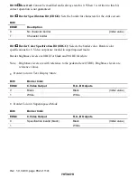
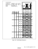
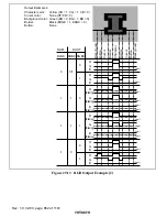
YCO Digital Output Specification Bit (YCOC): Specifies the YCO digital output
format. This bit must be reset to 0 when bordering is not performed, and must be set to 1 when
bordering is performed.
Bit 5
YCOC
Description
0
Character output is specified
(Initial value)
1
Combined character and border output is specified
Bit 4
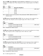
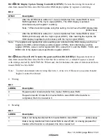
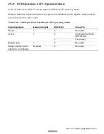
Digital Output Blink Control Bit (DOBC): Turns blinking on and off for digital outputs
(YCO, R, G, and B). Digital output YBO cannot be made to blink.
OSDRAM
DOUT
Bit 15
Bit 4
BLNK
DOBC
Description
0
Does not blink
(Initial value)
0
1
Does not blink
0
Does not blink
1
1
Blinks
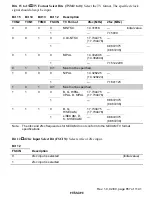
Bit 3
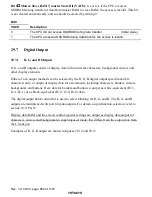
R, G, B, YCO, YBO Pin Function Select Bit (DSEL): Selects the R, G, B, YCO, and
YBO pins to function either as digital output pins, or as data slicer internal monitor signal pins.
Bit 3
DSEL
Description
0
R, G, B, YCO, YBO output function is selected
(Initial value)
1
Data slicer monitor output function is selected
R pin = Signal selected by bit 2 (CRSEL)
G pin = Slice data signal analog-compared with Cvin2
B pin = Sampling clock generated within data slicer
YCO pin = External Hsync signal (AFCH) synchronized within the LSI
YBO pin = External Vsync signal (AFCV) synchronized within the LSI


