Rev. 1.0, 02/00, page 295 of 1141
Bit 7
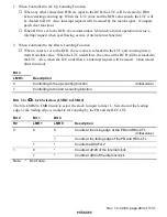
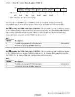
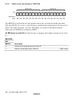
Capture Signals of the TMRU-2 (LAT): In combination with the CPS bit (Bit 0) of the
TMRM1, this bit works to select the capture signals of the TMRU-2.
TMRM2
TMRM1
Bit 7
Bit 0
LAT
CPS
Description
0
*
Captures when the TMRU-3 underflows
(Initial value)
0
Captures at the rising edge of the CFG
1
1
Captures at the edge of the IRQ3
Note:
*
Don't care.
Bits 6 and 5
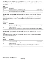
Clock Source for the TMRU-1 (PS11 and PS10): These bits work to select the
inputting clock to the TMRU-1.
Bit 6
Bit 5
PS11
PS10
Description
0
Counting at the rising edge of the CFG
(Initial value)
0
1
Counting by the PSS,
φ
/4
0
Counting by the PSS,
φ
/256
1
1
Counting by the PSS,
φ
/512
Bits 4 and 3
Clock Source for the TMRU-3 (PS31 and PS30)
These bits work to select the inputting clock to the TMRU-3.
Bit 4
Bit 3
PS31
PS30
Description
0
Counting at the rising edge of the DVCTL from the dividing circuit.
(Initial value)
0
1
Counting by the PSS,
φ
/4096
0
Counting by the PSS,
φ
/2048
1
1
Counting by the PSS,
φ
/1024

