Rev. 1.0, 02/00, page 911 of 1141
30.3.4
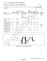
Serial Interface Timing of HD64F2199
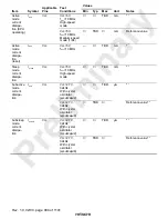
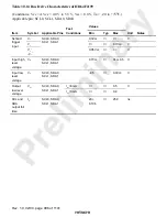
Table 30.17 Serial Interface Timing of HD64F2199
(Conditions: Vcc = AVcc = 4.0 V to 5.5 V, Vss = 0.0 V, Ta = –20 to +75
°
C unless otherwise
specified.)
Values
Item
Symbol
Applicable
Pins
Test
Conditions
Min
Typ
Max
Unit
Figure
Asynchroniza-
tion
4
Input clock cycle
t
scyc
SCK1
Clock
synchronization
6
t
cyc
Input clock pulse
width
t
SCKW
SCK1
0.4
0.6
t
scyc
Input clock rise time
t
SCKr
SCK1
1.5
t
cyc
Input clock fall time
t
SCKf
SCK1
1.5
t
cyc
Figure
30.15
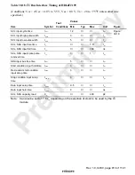
Transmit data delay
time (clock sync)
t
TXD
SO1
100
ns
Receive data setup
time (clock sync)
t
RXS
SI1
100
ns
Receive data hold
time (clock sync)
t
RXH
SI1
100
ns
Figure
30.16
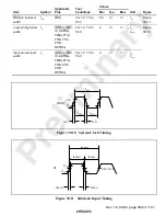
t
SCKf
t
SCKr
V
IL
or V
OL
V
IH
or V
OH
SCK1
t
SCKW
t
scyc
Figure 30.15 SCK1 Clock Timing

