Rev. 1.0, 02/00, page 634 of 1141
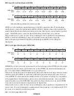
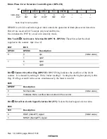
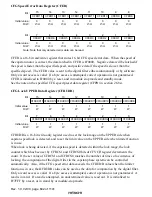
Drum Phase Error Detection Control Register (DPGCR)
0
1
1
2
—
—
—
—
—
—
1
3
0
4
0
R/W
R/W
5
0
6
0
7
R/(W)*
DPOVF
R/W
DPCS0
0
R/W
DPCS1
N/V
HSWES
1
Bit :
Initial value :
R/W :
Note: Only 0 can be written.
DPGCR is an 8-bit read/write register that controls the operation of drum phase error detection.
Bits 2-0 are reserved, bit 5 accepts only read and 0 write.
It is initialized to H'07 by a reset or in stand-by mode.
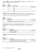
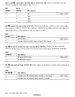
Bits 7 and 6
Clock Source Selection Bit (DPCS1, DPCS0): These bits select the clock
supplied to the counter. (
φ
s = fosc/2)
Bit 7
Bit 6
DPCS1
DPCS0
Description
0
φ
s
(Initial value)
0
1
φ
s/2
0
φ
s/4
1
1
φ
s/8
Bit 5
Counter Overflow Flag (DPOVF): DPOVF flag indicates the overflow of the 20-bit
counter. It is cleared by writing 0. Write 0 after reading 1. Setting has the highest priority in this
flag. If a flag set and 0 write occurs simultaneously, the latter is invalid.
Bit 5
DPOVF
Description
0
Normal state
(Initial value)
1
Indicates that a overflow has occurred in the counter
Bit 4
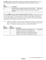
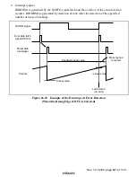
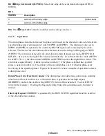
Error Data Latch Signal Selection Bit (N/V): Selects the latch signal of error data.
Bit 4
N/V
Description
0
HSW (VideoFF) signal
(Initial value)
1
NHSW (NarrowFF) signal


