Rev. 1.0, 02/00, page 735 of 1141
26.15.3
Pin Configuration
Table 26.25 shows the pin configuration of the sync signal detector.
Table 26.25 Pin Configuration
Name
Abbrev.
I/O
Function
Composite sync signal input pin
Csync
Input
Composite sync signal input
26.15.4
Register Configuration
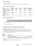
Table 26.26 shows the register configuration of the sync signal detector.
Table 26.26 Register Configuration
Name
Abbrev.
R/W
Size
Initial Value
Address
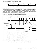
Vertical sync signal
threshold register
VTR
W
Byte
H'C0
H'D0B0
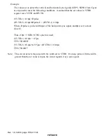
Horizontal sync signal
threshold register
HTR
W
Byte
H'F0
H'D0B1
H complement start time
setting register
HRTR
W
Byte
H'00
H'D0B2
Complement H pulse
width setting register
HPWR
W
Byte
H'F0
H'D0B3
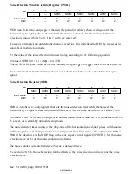
Noise detection window
setting register
NWR
W
Byte
H'C0
H'D0B4
Noise detector
NDR
W
Byte
H'00
H'D0B5
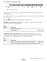
Sync signal control
register
SYNCR
R/W
Byte
H'F8
H'D0B6


