Rev. 1.0, 02/00, page 107 of 1141
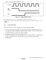
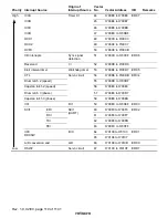
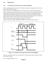
Figure 6.3 shows the timing of IRQnF setting.
Internal
φ
IRQnF
IRQn
input pin
Figure 6.3 Timing of IRQnF Setting
The vector
num bers for IRQ 5 to IRQ 0 interrupt exception handling are 21 to 26.
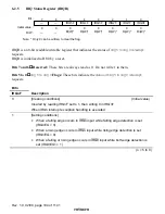
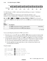
U pon detection of IRQ 5 to IRQ 0 interrupts, the applicable pin is set in the port register 1 (PM R1)
as
,54Q
pin.
6.3.2
Internal Interrupts
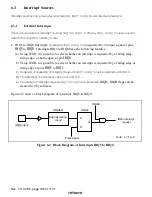
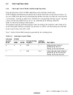
There are 38 sources for internal interrupts from on-chip supporting modules.
•
For each on-chip supporting module there are flags that indicate the interrupt request status,
and enable bits that select enabling or disabling of these interrupts. If any one of these is set to
1, an interrupt request is issued to the interrupt controller.
•
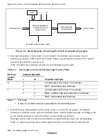
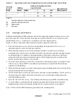
The interrupt control level can be set by means of ICR.
•
The NMI is the highest priority interrupt and is always accepted regardless of the control mode
and CPU interrupt mask bit. In this LSI, NMIs are used as interrupts generated by the
watchdog timer


