Rev. 1.0, 02/00, page 283 of 1141
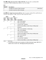
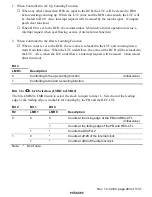
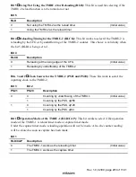
1. When Controlled to the Up-Counting Function
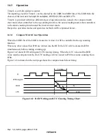
When any other values than H'00 are input to the RCR, the LTC will be cleared to H'00
before starting counting up. When the LTC value and the RCR value match, the LTC will
be cleared to H'00. Also, interrupt requests will be issued by the match signal. (Compare
patch clear function)
When H'00 is set to the RCR, the counter makes 8-bit interval timer operation to issue a
interrupt request when overflowing occurs. (Interval timer function)
2. When Controlled to the Down-Counting Function
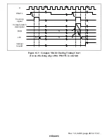
When a value is set to the RCR, the set value is reloaded to the LTC and counting down
starts from that value. When the LTC underflows, the value of the RCR will be reloaded to
the LTC. Also, when the LTC underflows, a interrupt request will be issued. (Auto reload
timer function)
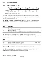
Bit 3
LMR3
Description
0
Controlling to the up-counting function
(Initial value)
1
Controlling to the down-counting function
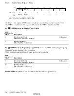
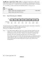
Bits 2 to 0
Clock Selection (LMR2 to LMR0)
The bits LMR2 to LMR0 work to select the clock to input to timer L. Selection of the leading
edge or the trailing edge is workable for counting by the PB and the REC-CTL.
Bit 2
Bit 1
Bit 0
R2
LMR1
LMR0
Description
0
Counts at the rising edge of the PB and REC-CTL
(Initial value)
0
1
Counts at the falling edge of the PB and REC-CTL
0
1
*
Counts the DVCFG2
0
*
Counts at
φ
/128 of the internal clock
1
1
*
Counts at
φ
/64 of the internal clock
Note:
*
Don't care.

