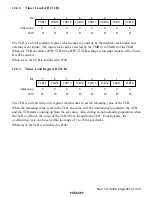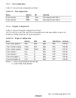
Rev. 1.0, 02/00, page 265 of 1141
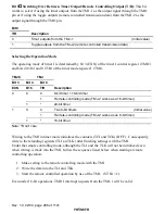
Bit 5
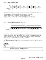
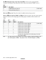
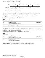
Starting the Remote Controlled Operation (ST): This bit works to start the remote
controlled operations.
When this bit is set to 1, clock signal is supplied to the TMJ-1 to start signal transmissions.
When this bit is cleared to 0, clock supply stops to discontinue the operation. The ST bit will be
valid under the remote controlling mode, namely, when bit 0 (T/R bit) is 1 and bit 4 (8/16 bit) is 0.
Under other modes than the remote controlling mode, it will be fixed to 0. When a shift to the low
power consumption mode is made during remote controlled operation, the ST bit will be cleared to
0. When resuming operation after returning to the active mode, write 1.
Bit 5
ST
Description
0
Works to stop clock signal supply to the TMJ-1 under the remote controlling mode
(Initial value)
1
Works to supply clock signal to the TMJ-1 under the remote controlling mode
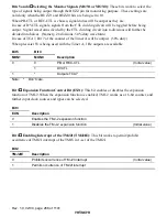
Bit 4
Switching Over Between 8-bit/16-bit Operations (8/16): This bit works to choose if
using timer J as two units of 8-bit timer/counter or if using it as a single unit of 16-bit
timer/counter. Even under 16-bit operations, TMJ1I interrupt requests from the TMJ-1 will be
valid.
Bit 4
8/16
Description
0
Makes the TMJ-1 and TMJ-2 operate separately
(Initial value)
1
Makes the TMJ-1 and TMJ-2 operate altogether as 16-bit timer/counter
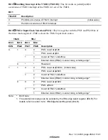
Bits 3 and 2
Selecting the Inputting Clock for the TMJ-2 (PS21 and PS20): These bits,
together with the PS22 bit in the timer J control register (TMJC), work to select the clock for the
TMJ-2. When the external clock is selected, the counted edge (rising or falling) can also be
selected. For details, refer to section 13.2.2, Timer J Control Register (TMJC).
Bit 1
TMJ-2 Toggle Flag (TGL): This flag indicates the toggled status of the underflowing
with the TMJ-2. Reading only is workable.
It will be cleared to 0 under the low power consumption mode.
Bit 1
TGL
Description
0
The toggle output of the TMJ-2 is 0
(Initial value)
1
The toggle output of the TMJ-2 is 1

