Rev. 1.0, 02/00, page 300 of 1141
15.2.5
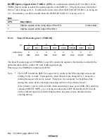
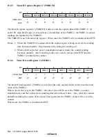
Timer R Capture Register 2 (TMRCP2)
0
1
1
1
2
1
3
1
4
1
5
1
6
1
7
1
R
TMRC27
R
TMRC26
R
TMRC25
R
TMRC24
R
TMRC23
R
TMRC22
R
TMRC21
R
TMRC20
Bit :
Initial value :
R/W :
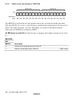
The timer R capture register 2 (TMRCP2) works to store the capture data of the TMRU-2. At
each CFG edge, IRQ3 edge, or at occurrence of underflow of the TMRU-3, the TMRU-2 counter
readings are captured by the TMRCP2.
The TMRCP2 is an 8-bit read only register. When reset, the TMRCS will be initialized into H'FF.
Notes: 1. When the TMRCP2 is readout while the capture signal is being received, the reading
data become unstable. Pay attention to the timing for reading out.
2. When a shift to the low power consumption mode is made, the counter reading
becomes unstable. After returning to the active mode, always write H'FF into the
TMRL2 to initialize the counter.
15.2.6
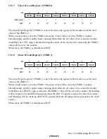
Timer R Load Register 1 (TMRL1)
0
1
1
1
2
1
3
1
4
1
5
1
6
1
7
1
W
TMR17
W
TMR16
W
TMR15
W
TMR14
W
TMR13
W
TMR12
W
TMR11
W
TMR10
Bit :
Initial value :
R/W :
The timer R load register 1 (TMRL1) is an 8-bit write-only register which works to set the load
value of the TMRU-1.
When a load value is set to the TMRL1, the same value will be set to the TMRU-1 counter
simultaneously and the counter starts counting down from the set value. Also, when the counter
underflows during the course of the reload timer operation, the TMRL1 value will be set to the
counter.
When reset, the TMRL1 is initialized to H'FF.

