Rev. 1.0, 02/00, page 390 of 1141
21.2
Registers
21.2.1
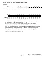
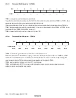
Input Capture Register 1 (ICR1)
0
0
1
0
R
2
0
R
3
0
4
0
R
0
R
5
6
0
7
ICR14
ICR13
ICR12
ICR11
ICR10
0
R
ICR17
R
R
R
ICR16
ICR15
Bit :
Initial value :
R/W :
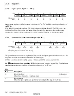
Input capture register 1 (ICR1) captures 8-bit data of 2
15
to 2
8
of the FRC according to the edge of
the
,&
pin.
ICR1 is an 8-bit read-only register. The write operation becomes invalid. The ICR1 values are
undefined until the first capture is generated after the mode has been set to the standby mode,
watch mode, subactive mode, and subsleeve mode. When reset, ICR1 is initialized to H'00.
21.2.2
Prescalar Unit Control/Status Register (PCSR)
0
0
1
0
R/W
2
0
R/W
3
—
—
1
4
0
R/W
5
0
6
0
7
R/W
R/W
ICEG
R/W
ICIE
0
R/(W)*
ICIF
NCon/off
DCS2
DCS1
DCS0
Note: * Only 0 can be written to clear the flag.
Bit :
Initial value :
R/W :
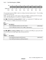
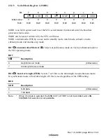
The prescalar unit control/status register (PCSR) controls the input capture function and selects the
frequency division clock that is output from the TMOW pin.
PCSR is an 8-bit read/write enable register. When reset, PCSR is initialized to H'08.
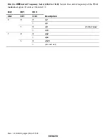
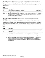
Bit 7
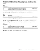
Input Capture Interrupt Flag (ICIF): Input capture interrupt request flag. This indicates
that the input capture was performed according to the edge of the
,&
pin.
Bit 7
ICIF
Description
0
[Clear condition]
(Initial value)
When 0 is written after 1 has been read
1
[Set condition]
When the input capture was performed according to the edge of the
,&
pin

