


Rev. 1.0, 02/00, page 689 of 1141
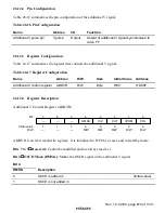
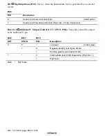
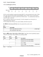
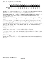
CTL Mode Register (CTLM)
0
0
1
0
R/W
2
0
R/W
3
0
4
0
R/W
5
0
6
0
7
R/W
R/W
R/W
FW/RV
R/W
REC/PB
0
R/W
ASM
MD4
MD3
MD2
MD1
MD0
Bit :
Initial value :
R/W :
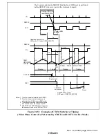
CTLM is an 8-bit read/write register that controls the operating state of the CTL circuit. If 1 is
written in bits MD3 and MD2, they will be cleared to 0 one cycle (
φ
) later.
CTLM is initialized to H'00 by a reset, and in standby mode and module stop mode. When CTL is
being stopped, only bits 7, 6 and 5 operate.
Note:
Do not set any value other than the setting value for each mode (see table 26.20, CTL
Mode Functions).
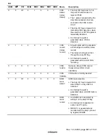
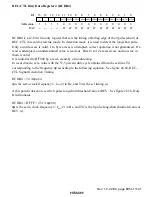
Bits 7 and 6
Record/Playback Mode Bits (ASM, REC/
3%
3%
3%
3%
): These bits switch between record
and playback. Combined with bits 4 to 0 (MD4 to MD0), they support the VISS, VASS, and
ASM mark functions.
Bit 7
Bit 6
ASM
REC/
3%
3%
3%
3%
Description
0
Playback mode
(Initial value)
0
1
Record mode
0
Assemble mode
1
1
Invalid (do not set)
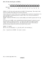
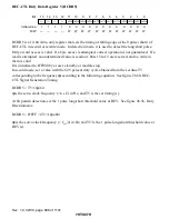
Bit 5
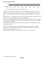
Direction (FW/RV): Selects the direction in playback. Clear this bit to 0 during record.
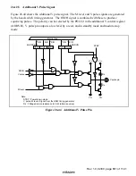
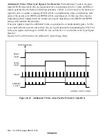
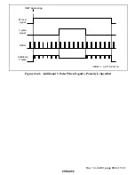
Figure 26.48 shows the PB-CTL signal.
Bit 5
FW/RV
Description
0
Forward
(Initial value)
1
Reverse