Rev. 1.0, 02/00, page 813 of 1141
28.2.6
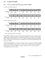
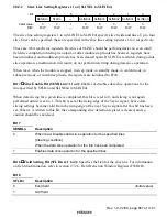
Monitor Output Setting Register (DOUT)
0
1
1
1
—
2
0
R/W
3
0
4
1
R/W
0
R/W
5
6
0
7
DOBC
DSEL
CRSEL
—
—
0
—
—
—
R/W
R/W
RGBC
YCOC
Bit:
Initial value:
R/W:
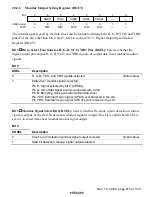
The internal signals used by the data slicer can be monitored through the R, G, B, YCO, and YBO
pins. For the bits other than bits 2 and 3, refer to section 29.7.3, Digital Output Specification
Register (DOUT).
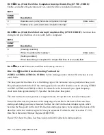
Bit 3
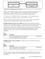
Bit to Select Functions for R, G, B, YCO, YBO Pins (DSEL): Selects whether the
digital output pins output R, G, B, YCO, and YBO signals, or output data slicer internal monitor
signals.
Bit 3
DSEL
Description
0
R, G, B, YCO, and YBO signals selected
(Initial value)
1
Data slicer monitor signals selected
Pin R: Signal selected by bit 2 (CRSEL)
Pin G: Slice data signal analog-compared with Cvin2
Pin B: Sampling clock generated within data slicer
Pin YCO: External Hsync signal (AFCH) synchronized in the LSI
Pin YBO: External Vsync signal (AFCV) synchronized in the LSI
Bit 2
Monitor Signal Select Bit (CRSEL): Selects whether the clock run-in detection window
signal is output, or the start bit detection window signal is output. This bit is valid when DSEL is
set to 1 to select data slicer internal monitor signal output.
Bit 2
CRSEL
Description
0
Clock run-in detection window signal output selected
(Initial value)
1
Start bit detection window signal output selected


