Rev. 1.0, 02/00, page 202 of 1141
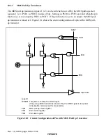
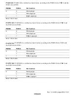
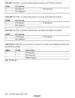
P23/SDA1: P23/SDA1 is switched as shown below according to the PCR23 bit in PCR2 and the
II1CE bit in the I
2
C Bus control register (ICCR1).
II1CE
PCR23
Pin Function
0
P23 input pin
0
1
P23 output pin
1
*
SDA1 I/O pin
Note:
*
Don’t care
P22/SCK1: P22/SCK1 is switched as shown below according to the PCR22 bit in PCR2, the C/
$
bit in SMR, and the CKE1 and CKE0 bits in SCR.
CKE1
C/
$
$$
$
CKE0
PCR22
Pin Function
0
P22 input pin
0
1
P22 output pin
0
1
0
1
SCK1 output pin
1
*
*
*
SCK1 input pin
Note:
*
Don’t care
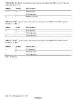
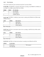
P21/SO1: P21/SO1 is switched as shown below according to the PCR21 bit in PCR2 and the TE
bit in SCR.
TE
PCR21
Pin Function
0
P21 input pin
0
1
P21 output pin
1
*
SO1 output pin
Note:
*
Don’t care
P20/SI1: P20/SI1 is switched as shown below according to the PCR20 bit in PCR2 and the RE bit
in SCR.
RE
PCR20
Pin Function
0
P20 input pin
0
1
P20 output pin
1
*
SI1 input pin
Note:
*
Don’t care

