Rev. 1.0, 02/00, page x of 19
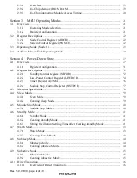
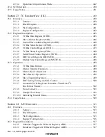
17.3.2
Interval Timer Operation .................................................................................. 356
17.3.3
Timing of Setting of Overflow Flag (OVF)...................................................... 357
17.4
Interrupts ........................................................................................................................... 358
17.5
Usage Notes ...................................................................................................................... 358
17.5.1
Contention between Watchdog Timer Counter (WTCNT)
Write and Increment ......................................................................................... 358
17.5.2
Changing Value of CKS2 to CKS0 .................................................................. 359
17.5.3
Switching between Watchdog Timer Mode and Interval Timer Mode ............ 359
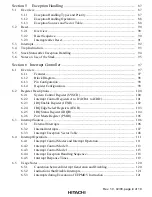
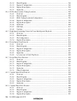
Section 18 8-Bit PWM
....................................................................................................... 361
18.1
Overview........................................................................................................................... 361
18.1.1
Features............................................................................................................. 361
18.1.2
Block Diagram.................................................................................................. 361
18.1.3
Pin Configuration ............................................................................................. 362
18.1.4
Register Configuration...................................................................................... 362
18.2
Register Descriptions ........................................................................................................ 363
18.2.1
8-bit PWM Data Registers 0, 1, 2 and 3 (PWR0, PWR1, PWR2, PWR3) ....... 363
18.2.2
8-bit PWM Control Register (PW8CR) ............................................................ 364
18.2.3
Port Mode Register 3 (PMR3) .......................................................................... 365
18.2.4
Module Stop Control Register (MSTPCR)....................................................... 366
18.3
8-Bit PWM Operation ....................................................................................................... 367
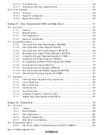
Section 19 12-Bit PWM
.................................................................................................... 369
19.1
Overview........................................................................................................................... 369
19.1.1
Features............................................................................................................. 369
19.1.2
Block Diagram.................................................................................................. 370
19.1.3
Pin Configuration ............................................................................................. 371
19.1.4
Register Configuration...................................................................................... 371
19.2
Register Descriptions ........................................................................................................ 372
19.2.1
12-Bit PWM Control Registers (CPWCR, DPWCR) ....................................... 372
19.2.2
12-Bit PWM Data Registers (DPWDR, CPWDR) ........................................... 375
19.3
Operation .......................................................................................................................... 376
19.3.1
Output Waveform ............................................................................................. 376
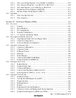
Section 20 14-Bit PWM
.................................................................................................... 379
20.1
Overview........................................................................................................................... 379
20.1.1
Features............................................................................................................. 379
20.1.2
Block Diagram.................................................................................................. 380
20.1.3
Pin Configuration ............................................................................................. 380
20.1.4
Register Configuration...................................................................................... 381
20.2
Register Descriptions ........................................................................................................ 382
20.2.1
PWM Control Register (PWCR) ...................................................................... 382
20.2.2
PWM Data Registers U and L (PWDRU, PWDRL)......................................... 383

