Rev. 1.0, 02/00, page 805 of 1141
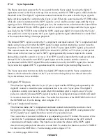
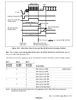
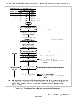
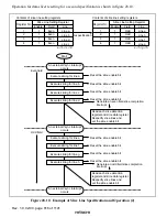
Clock run-in
Data slicer base point
Clock run-in detection
window signal
Start bit detection
window signal
Data slicer
base point
Base point for start bit
detection starting position
Approx. 23.5
µ
s
Start bit detectable
period
TS
Te = Approx. 29.5
µ
s
1
288
×
fh
TS = 23.5
µ
s +
µ
s
×
(Set by STB4 to STB0)
C.video
S1 S2 S3
Start
bit
Set by STB
Figure 28.2 Data Slicer Base Point and Start Bit Detection Starting Position
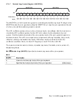
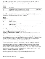
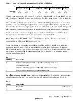
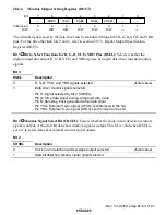
Bits 7 to 5—Slice Level Setting Bits (SLVLE2 to SLVLE0) (SLVLO2 to SLVLO0): Specify
the even (odd) field data slice level.
The data slice level is common to clock line detection, start bit detection, and 16-bit data slicing.
Bit 7
Bit 6
Bit 5
SLVLE2
SLVLO2
SLVLE1
SLVLO1
SLVLE0
SLVLO0
Description
0
Slice level is 0 IRE
(Initial value)
0
1
Slice level is 5 IRE
0
Slice level is 15 IRE
0
1
1
Slice level is 20 IRE
0
Slice level is 25 IRE
0
1
Slice level is 35 IRE
0
Slice level is 40 IRE
1
1
1
Must not be specified
Note:
All slice levels are with reference to the pedestal level (5 IRE). Slice level values are
provided for reference.

