Rev. 1.0, 02/00, page 874 of 1141
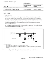
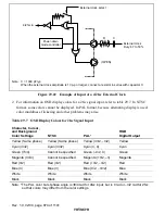
Power-down
mode controller
External clock
Duty: 47 to 53%
4/2fsc in
C
R
(OPEN)
Note: C = 1000 pF typ
When the external clock amplitude is 1 Vp-p or larger, connect a resistor in series with capacitor C.
External clock select
Figure 29.22 Example of Input of a 4/2fsc External Clock
2. For information on OSD display colors for a 2fsc signal input, refer to table 29.7. In NTSC
format, some colors cannot be displayed. In PAL format, because alternating display is used,
color muddiness, flickering and other problems may arise.
Table 29.7
OSD Display Colors for 2fsc Signal Input
Character, Cursor,
and Background
Color Settings
NTSC
PAL
*
RGB
Digital Output
Yellow (Same phase)
Yellow (Same phase)
Yellow (3
π
/2, –
π
/2)
Yellow
Cyan (3
π
/2)
Cyan (3
π
/2)
Cyan (
π
, 0)
Cyan
Green (7
π
/4)
Cannot be specified
Green (–
π
/2, 0)
Green
Magenta (3
π
/4)
Cannot be specified
Magenta (+
π
/2, –
π
)
Magenta
Red (
π
/2)
Red (
π
/2)
Red (+
π
/2, –
π
/2)
Red
Blue (
π
)
Blue (
π
)
Blue (
π
/2, –3
π
/2)
Blue
White
White
White
White
Black
Black
Black
Black
Note:
*
The PAL color burst phase angle is
±π
/4 rad for 4fsc input, but is 0 rad or –
π
/2 rad for 2fsc,
so that colors may differ from the color settings.

