Rev. 1.0, 02/00, page 500 of 1141
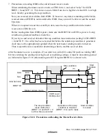
SDA
(Slave output)
SDA
(Master output)
SCL
(Slave output)
2
1
2
1
4
3
6
5
8
7
9
9
8
Bit 7
Bit 6
Bit 5
Bit 7
Bit 6
Bit 4
Bit 3
Bit 2
Bit 1
Bit 0
IRIC
ICDRS
ICDRT
TDRE
SCL
(Master output)
Interrupt
request
generated
Interrupt
request
generated
Interrupt
request
generated
Slave receive mode
Slave transmit mode
Data 1
Data 2
[3] Clear IRIC
[5] Clear IRIC
[3] Write ICDR
[3] Write ICDR
[5] Write ICDR
User
processing
Data 1
Data 1
Data 2
Data 2
A
R/W
A
[3]
[2]
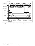
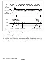
Figure 23.11 Example of Timing in Slave Transmit Mode (MLS = 0)
23.3.6
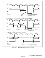
IRIC Setting Timing and SCL Control
The interrupt request flag (IRIC) is set at different times depending on the WAIT bit in ICMR, the
FS bit in SAR, and the FSX bit in SARX. If the TDRE or RDRF internal flag is set to 1, SCL is
automatically held low after one frame has been transferred; this timing is synchronized with the
internal clock. Figure 23.12 shows the IRIC set timing and SCL control.

