Rev. 1.0, 02/00, page 224 of 1141
10.7.3
Pin Functions
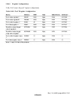
This section describes the port 6 pin functions and their selection methods.
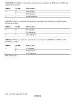
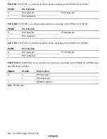
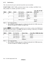
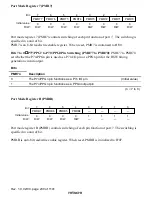
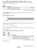
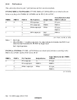
P67/RP7/TMBI: P67/RP7/TMBI is switched as shown below according to the PMRA7 bit in
PMRA, PMR67 bit in PMR6, and PCR67 bit in PCR6.
PMRA7
PMR67
PCR67
Pin Function
Output Value
Value When PDR6n
Was Read
0
P67 input pin
P67 pin
0
1
P67 output pin
PDR67
PDR67
0
Hi-Z
*
1,
*
2
0
1
1
RP7 output pin
PDRS67
*
2
PDR67
0
P67 pin
1
*
1
TMBI input pin
PDR67
Notes: 1. Hi-Z: High impedance
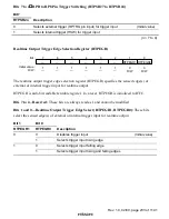
2. When PMR67=1 (realtime output pin), indicates the state after the PCR67 setup value
has been transferred to PCRS67 by a trigger input.
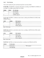
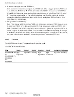
P66/RP6/
$'75*
$'75*
$'75*
$'75*
: P66/RP6/
$'75*
is switched as shown below according to the PMR66 bit in
PMR6 and PCR66 bit in PCR6. The
$'75*
pin function switching is controlled by the ADTSR.
For details, refer to section 24, A/D converter.
PMR66
PCR66
Pin Function
Output Value
Value When PDR66 Was Read
0
P66 input pin
P67 pin
0
1
P66 output pin
PDR66
PDR66
0
Hi-Z
*
1,
*
2
1
1
RP6 output pin
PDRS66
*
2
PDR66
Notes: 1. Hi-Z: High impedance
2. When PMR66=1 (realtime output pin), indicates the state after the PCR66 setup value
has been transferred to PCRS66 by a trigger input.

