Rev. 1.0, 02/00, page 691 of 1141
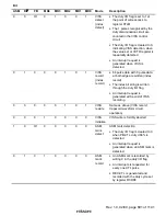
Bit
ASM
R/
3
33
3
F/R
MD4
MD3
MD2
MD1
MD0
Mode
Description
0
0
0/1
0
1
0
0
1
VISS
detect
(index
detect)
•
The duty I/O flag is set to 1 at
the point of write access to
register CTLM
•
The 1 pulses recognized by the
duty discrimination circuit are
counted in the VISS control
circuit
•
The duty I/O flag is cleared to 0,
indicating VISS detection, when
the value set at VCTR register is
repeatedly detected
•
An interrupt request is
generated when VISS is
detected
0
1
0
0
0
1
0
1
VISS
record
(index
record)
•
64 pulse data with 0 pulse data
at both edge are written (index
record)
•
The index bit string is written
through the duty I/O flag
•
An interrupt request is
generated at the end of VISS
recording
0
0
0
0
0
1
0
1
VISS
rewrite
Same as above (VISS record;
trapezoid waveform circuit
operation)
0
0
0
1
0
0
0
0
VISS
initialize
VISS write is forcibly aborted
1
0
0/1
0
0
0
0
0
ASM
mark
detect
ASM mark detection
•
The duty I/O flag is cleared to 0
when PB-CTL duty
≥
66% is
detected
•
An interrupt request is
generated when an ASM mark is
detected
0
1
0
1
0
0
0
0
ASM
mark
record
•
An ASM mark is recorded by
writing 0 in the duty I/O flag
•
An interrupts is requested for
every one CTL pulse
•
REC-CTL is generated and
recorded with the duty cycle set
by register RCDR3


