Rev. 1.0, 02/00, page 635 of 1141
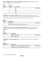
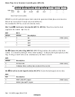
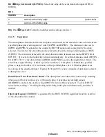
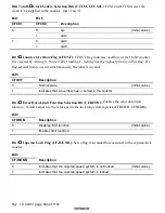
Bit 3
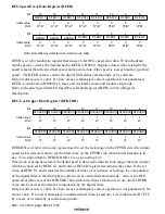
Edge Selection Bit (HSWES): Selects the edge of the error data latch signal (HSW or
NHSW).
Bit 3
HSWES
Description
0
Latches at the rising edge
(Initial value)
1
Latches at the falling edge
Bits 2 to 0
Reserved: Cannot be modified and are always read as 1.
26.7.5
Operation
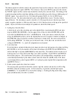
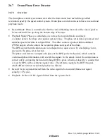
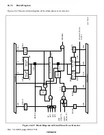
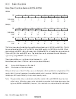
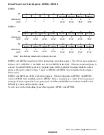
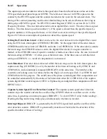
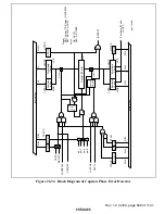
The drum phase error detector detects the phase error based on the reference value set in the drum
specified phase preset data registers 1 and 2 (DPPR1 and DPPR2). The reference values set in
DPPR1 and DPPR2 are preset in the counter by REF30P signal, and counted up by the clock
selected. The latch of the error data can be selected between the rising or falling edge of HSW
(NHSW). The error data detected in the error data automatic transmission mode (DFEPS bit of
DFUCR = 0) is sent to the digital filter circuits automatically. In soft transmission mode (DFEPS
bit of DFUCR = 1), the data written in DPER1 and DPER2 is sent to the digital filter circuit. The
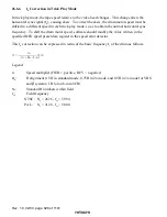
error data is signed binary. It takes a positive number (+) if the phase is behind the specified
phase, a negative number (-) if in advance of the specified phase, or 0 if it had no phase error
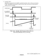
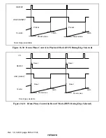
(revolving at the specified phase). Figures 26.30 and 26.31 show examples of operation to detect
a drum phase error.
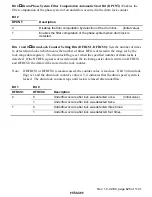
Drum Phase Error Detection Counter: The drum phase error detection counter stops counting
when an overflow or latch occurs. At the same time, it generates an interrupt request
(IRRDRM3), and sets the overflow flag (DPOVF) if an overflow occurred. To clear DPOVF,
write 0 after reading 1. If setting the flag and writing 0 take place simultaneously, the latter is
invalid.
Interrupt Request: IRRDRM3 is generated by the HSW (NHSW) signal latch and the overflow
of the error detection counter.


