Functions
6-309
7SA6 Manual
C53000-G1176-C156-2
Remote Measured
Values
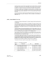
During communication, the data of the other ends of the protected object can also be
read out. For each of the devices, the currents and voltages involved as well as phase
shifts between the local and transfer measured quantities can be displayed. This is
especially helpful for checking the correct and coherent phase allocation at the
differrent line ends. Furthermore, the device addresses of the other devices is
transmitted so that all important data of all ends are available in the substation. All
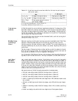
possible data are listed in Table 6-18.
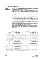
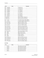
S, P, Q
apparent, real, and reactive pow-
er
MVA,
MW,
MVAR
—
√
3·U
N
·I
N
rated operational values
1
)
2
)
cos
ϕ
power factor
(abs)
(abs)
—
f
frequency
Hz
Hz
rated frequency
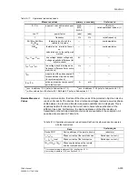
Θ
L1
/
Θ
trip
,
Θ
L2
/
Θ
trip
,
Θ
L3
/
Θ
trip
thermal value of each line
related to trip value
—
—
overtemperature
Θ
/
Θ
trip
thermal value, related to trip val-
ue,
calculated acc. to the configured
method
—
—
overtemperature
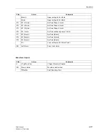
U
line
, U
sync
, U
diff
line voltage, busbar voltage and
voltage magnitude difference (for
synchro-check)
kV
—
—
f
line
, f
sync
, f
diff
line voltage, busbar voltage and
frequency difference (for synchro-
nism check)
Hz
—
—
ϕ
diff
magnitude of the phase angle dif-
ference between line and busbar
(for sychronism check)
°
—
—
I
EEa
, I
EEr
active and reactive component of
earth fault current
A
mA
—
Table 6-17
Operational measured values
Measured values
primary
secondary
% referred to
1
) acc. to address
1104
(refer to Sub-section 6.1.3)
2
) acc. to address
1103
(refer to Sub-section 6.1.3)
3
) with consideration of the factor
221
I4/Iph CT
(refer to Sub-section 6.1.1)
Tabelle 6-18 Operational measured values transmitted from the other ends and compared
with the local values
Data
% referring to
Device ADR
Device address of the remote device
(absolute)
I
L1
,I
L2
,I
L3
Phase currents of the remote device
Rated oper. current
1
)
I
L1
, I
L2
, I
L3
local
Phase currents of the local device
Rated oper. current
1
)
ϕ
(I
L1
),
ϕ
(I
L2
),
ϕ
(I
L3
)
Phase angles between the remote
and the local phase currents
°
1
) for lines according to address
1104
(see Section 6.1.3)
2
) according to address 1103 (see Section 6.1.3)
Summary of Contents for siprotec 7SA6
Page 2: ...Siemens Aktiengesellschaft Book No C53000 G1176 C156 2 ...
Page 18: ...xviii 7SA6 Manual C53000 G1176 C156 2 ...
Page 32: ...Introduction 1 14 7SA6 Manual C53000 G1176 C156 2 ...
Page 82: ...Hardware and Connections 2 50 7SA6 Manual C53000 G1176 C156 2 ...
Page 119: ...SIPROTEC 4 Devices 4 25 7SA6 Manual C53000 G1176 C156 2 Figure 4 20 CFC Logic example ...
Page 190: ...Configuration 5 62 7SA6 Manual C53000 G1176 C156 2 ...
Page 652: ...Installation and Commissioning 8 78 7SA6 Manual C53000 G1176 C156 2 ...
Page 724: ...Technical Data 10 56 7SA6 Manual C53000 G1176 C156 ...
Page 800: ...Appendix A 76 7SA6 Manual C53000 G1176 C156 2 ...
Page 866: ...Appendix B 66 7SA6 Manual C53000 G1176 C156 2 ...

