Functions
6-130
7SA6 Manual
C53000-G1176-C156-2
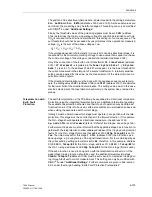
For the inverse time overcurrent stage 3I
0P
it is possible to select from a variety of
curves depending on the version of the relay and the configuration (Section 5.1, ad-
dress
131
) that was selected. If an inverse overcurrent stage is not required, the ad-
dress
131
is set to
Earth Fault O/C
=
Definite Time
. The 3I
0P
–stage can then
be used as a fourth definite time stage (refer to “Definite Time Stages” above) or de-
activated. In the case of the ANSI–curves (address
131
Earth Fault O/C
=
TOC
ANSI
) the following alternatives are available in the address
3151 ANSI Curve
:
Inverse
,
Short inverse
,
Long inverse
,
Moderately inv.
,
Very inverse
,
Extremely inv.
and
Definite inv.
The curves and equations the curves are based on are illustrated in the technical data
(Section 10.5, Figure 10-1 and 10-3).
The setting of the pick-up threshold
3I0p PICKUP
(address
3141
) is similar to the
setting of definite time stages (see above). In this case it must be considered that a
safety margin has already been included between the pick-up threshold and the set-
ting value. The stage only picks up when the measured signal is approximately 10 %
above the setting value.
The time multiplier setting
3I0p Time Dial
(address
3144
) is derived from the grad-
ing coordination chart which was set up for earth faults in the system.
In addition to the inverse current dependant time delay, a constant (fixed length) time
delay can also be set if this is required. The setting
Add.T-DELAY
(address
3147
) is
added to the time of the set curve.
Inverse Time
Overcurrent Stage
with Logarithmic–
Inverse
Characteristic
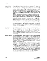
For the inverse time overcurrent stage with logarithmic inverse characteristic the op-
erating mode is initially set:
Op. mode 3I0p
(address
3140
). This stage can be set
to operate
Forward
(usually towards line) or
Reverse
direction (usually towards bus-
bar) or
Non-Directional
(in both directions). If this stage is not required, set its
mode to
Inactive
.
For the inverse logarithmic curves (address
131
Earth Fault O/C
=
TOC Loga-
rithm.
) the following can be set: address
3153
LOG Curve
=
Log. inverse.
The curves and equations the curves are based on are illustrated in the technical data
(Section 10.5, Figure 10-4). Figure 6-75 illustrates the influence of the most important
setting parameters on the curve.
3I0p PICKUP
(address
3141
) is the reference value
for all current values, while
3I0p Startpoint
(address
3154
) determines the be-
ginning of the curve, i.e. the lowest operating range on the current axis (referred to
3I0p PICKUP
). The timer setting
3I0p MaxT-DELAY
(address
3146
) determines
the starting point of the curve (for 3
I
0
=
3I0p PICKUP
). The time factor
3I0p Time
Dial
(address
3145
) changes the slope of the curve. For large currents,
3I0p
MinT-DELAY
(address
3142
) determines the lower limit on the time axis. For currents
larger than 30·
3I0p PICKUP
the operating time no longer decreases.
Finally in address
3147
Add.T-DELAY
a fixed time delay can be set as was done for
other curves. This, however, has almost the same effect on the characteristic as an
increase of
3I0p MaxT-DELAY
(address
3146
), but no effect on
3I0p MinT-DELAY
(address
3142
).
Summary of Contents for siprotec 7SA6
Page 2: ...Siemens Aktiengesellschaft Book No C53000 G1176 C156 2 ...
Page 18: ...xviii 7SA6 Manual C53000 G1176 C156 2 ...
Page 32: ...Introduction 1 14 7SA6 Manual C53000 G1176 C156 2 ...
Page 82: ...Hardware and Connections 2 50 7SA6 Manual C53000 G1176 C156 2 ...
Page 119: ...SIPROTEC 4 Devices 4 25 7SA6 Manual C53000 G1176 C156 2 Figure 4 20 CFC Logic example ...
Page 190: ...Configuration 5 62 7SA6 Manual C53000 G1176 C156 2 ...
Page 652: ...Installation and Commissioning 8 78 7SA6 Manual C53000 G1176 C156 2 ...
Page 724: ...Technical Data 10 56 7SA6 Manual C53000 G1176 C156 ...
Page 800: ...Appendix A 76 7SA6 Manual C53000 G1176 C156 2 ...
Page 866: ...Appendix B 66 7SA6 Manual C53000 G1176 C156 2 ...


