Hardware and Connections
2-45
7SA6 Manual
C53000-G1176-C156-2
Use only flexible copper control wire!
The following crimp connectors can be used:
Tin-plated version:
Diameter 0.5 mm
2
to 1.0 mm
2
:
e.g. Bandware 4000 pieces
type: 0–827039–1 from Messrs. Tyco Electronics AMP
Individual piece
type: 0–827396–1 from Messrs. Tyco Electronics AMP
Diameter 1.0 mm
2
to 2.5 mm
2
:
e.g. Bandware 4000 pieces
type: 0–827040–1 from Messrs. Tyco Electronics AMP
Individual piece
type: 0–827397–1 from Messrs. Tyco Electronics AMP
Connection of a conductor to a contact is performed using the following tools:
e.g. Hand crimping tool
type: 0–734372–1 from Messrs. Tyco Electronics AMP
Stencil
type: 1–734387–1 from Messrs. Tyco Electronics AMP
The use of individual pieces is recommended.
Gold-plated version (recommended):
Diameter 0.75 mm
2
to 1.5 mm
2
:
e.g. Bandware 4000 pieces
type: 0–163083–7 from Messrs. Tyco Electronics AMP
Individual piece
type: 0–163084–2 from Messrs. Tyco Electronics AMP
Connection of a conductor to a contact is performed using the following tools:
e.g. Hand crimping tool
type: 0–539635–1 from Messrs. Tyco Electronics AMP
Stencil
type: 1–539668–2 from Messrs. Tyco Electronics AMP
The use of individual pieces is recommended.
After the wires are crimped, the contacts are pressed into the terminals of the connec-
tor until they snap into place.
Stress relief for individual pin connector must be provided with cable ties. Stress relief
must also be provided for the entire set of cables, e.g., cable ties.
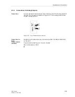
The following separation tool is needed to remove the contacts from the pin connec-
tors:
Type: 725840–1 from Messrs. Tyco Electronics AMP.
The separation tool contains a small tube that is subject to wear. The tube can be or-
dered separately:
Type: 725841–1 from Messrs. Tyco Electronics AMP.
2.3.4
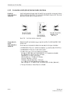
Connections to Optical Communication Interfaces
Optical Interfaces
ST–Connectors
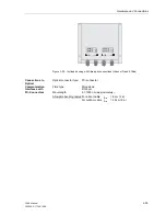
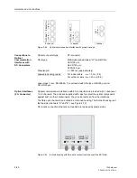
The three available versions of optical communication interfaces are shown in Figure
2-18. The ports are supplied with caps to protect the optical components against dust
or other contaminants. The caps can be removed by turning them 90° to the left.
Summary of Contents for siprotec 7SA6
Page 2: ...Siemens Aktiengesellschaft Book No C53000 G1176 C156 2 ...
Page 18: ...xviii 7SA6 Manual C53000 G1176 C156 2 ...
Page 32: ...Introduction 1 14 7SA6 Manual C53000 G1176 C156 2 ...
Page 82: ...Hardware and Connections 2 50 7SA6 Manual C53000 G1176 C156 2 ...
Page 119: ...SIPROTEC 4 Devices 4 25 7SA6 Manual C53000 G1176 C156 2 Figure 4 20 CFC Logic example ...
Page 190: ...Configuration 5 62 7SA6 Manual C53000 G1176 C156 2 ...
Page 652: ...Installation and Commissioning 8 78 7SA6 Manual C53000 G1176 C156 2 ...
Page 724: ...Technical Data 10 56 7SA6 Manual C53000 G1176 C156 ...
Page 800: ...Appendix A 76 7SA6 Manual C53000 G1176 C156 2 ...
Page 866: ...Appendix B 66 7SA6 Manual C53000 G1176 C156 2 ...


