Control During Operation
7-47
7SA6 Manual
C53000-G1176-C156-2
7.4.1
Display Equipment Position and Control
From the
DeviceFront
Devices with graphic display:
Devices with graphic display enable the user to read out the current switchgear posi-
tions in the default and control display. With the latter switchgears can also be control-
led. For this purpose use the three independent keys of different colours you can find
below the graphic display.
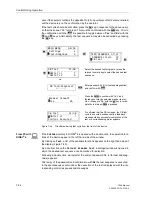
The
key is used to directly reach the control display.
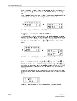
Select the required switchgear using the navigation keys
,
,
,
. To quit the
program during the selection process of switches or before tripping the command
press
.
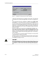
To define the switching direction press key
or key
.
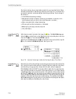
The circuit breaker symbol in the control display blinks when it is in the required posi-
tion. On the lower screen end you will be requested to confirm your decision.
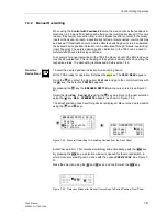
Press the
key. Then a safety query is carried out.
Confirm the safety query using the
key or quit the procedure with
.
Having confirmed the query, the actual switching activities can be initiated.
If the process has not been confirmed within one minute or if it was interrupted, the
blinking activitiy still indicating the required position goes back to the corresponding
actual status.
Under normal conditions the control display shows the new actual status after a
tripped switching command. At the lower screen end the message “
End of Com-
mand
” appears. For switching commands with feedback the message “
RM erreicht
“
appears shortly before the latter.
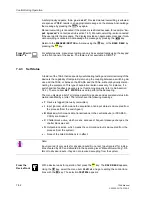
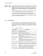
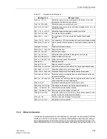
If the switching command is rejected because one interlocking condition could not be
fulfilled, the display shows a message informing the user about the reason of the re-
jection (see Subsection 7.4.8). The message must be cancelled with
to be able
to continue the operation of the device.
All devices:
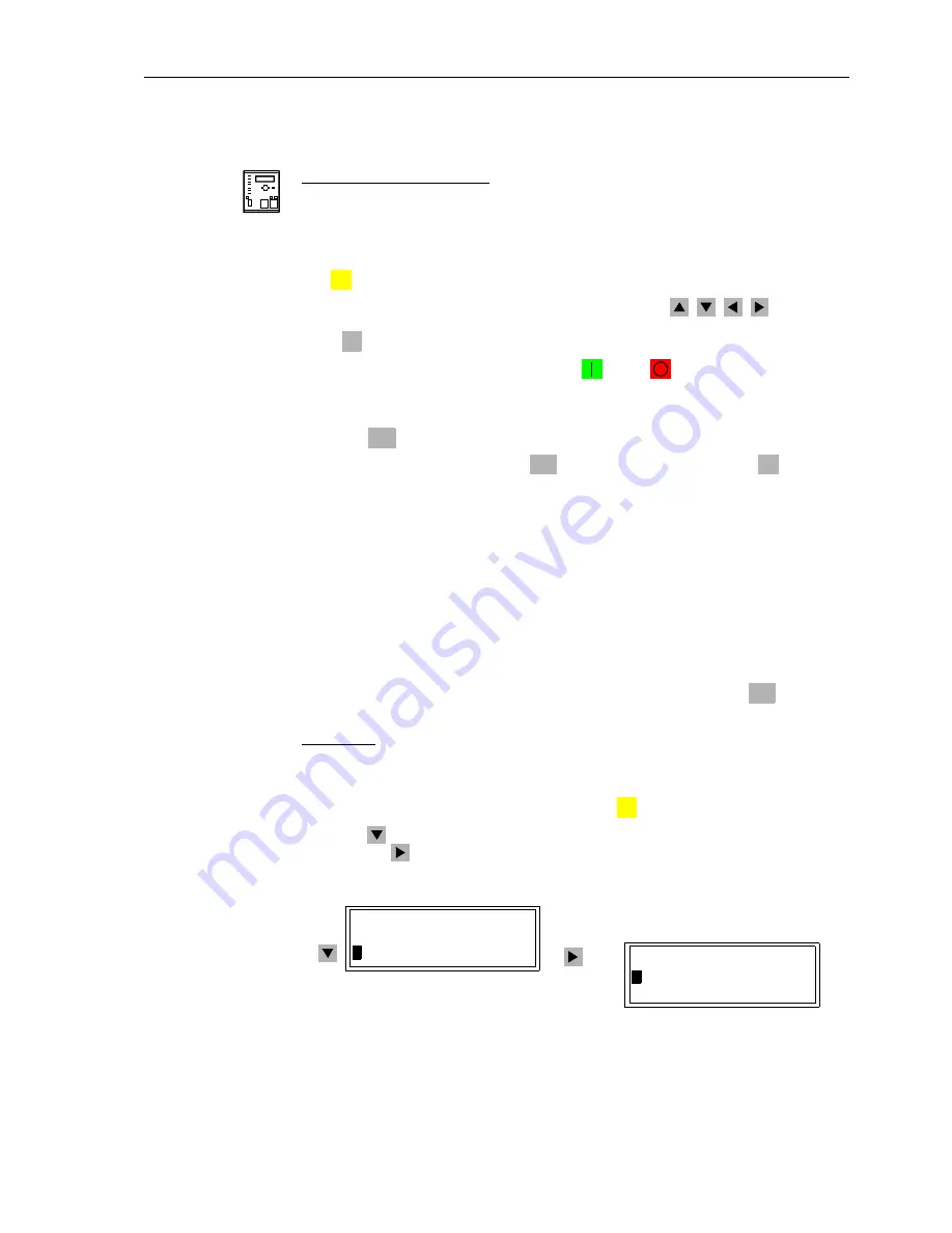
All devices provide the option to read out the circuit breaker positions and to control
switching commands via the display menus.
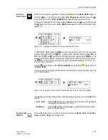
With a device ready for operation, first press the
key. The
MAIN MENU
appears.
Using the
key, select the menu item
Control
, and go to editing the control func-
tions with the
key. The selection
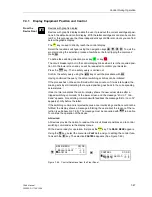
CONTROL
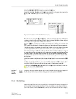
appears (See Figure 7-46).
Figure 7-46
Control Selections from the Front Panel
CTRL
ESC
ENTER
ENTER
ESC
ENTER
MENU
MAIN MENU 03/05
--------------------
Messurement –> 2
>
Control –> 3
CONTROL 01/03
--------------------
>
Breaker/Switch –> 1
Tagging –> 2
Summary of Contents for siprotec 7SA6
Page 2: ...Siemens Aktiengesellschaft Book No C53000 G1176 C156 2 ...
Page 18: ...xviii 7SA6 Manual C53000 G1176 C156 2 ...
Page 32: ...Introduction 1 14 7SA6 Manual C53000 G1176 C156 2 ...
Page 82: ...Hardware and Connections 2 50 7SA6 Manual C53000 G1176 C156 2 ...
Page 119: ...SIPROTEC 4 Devices 4 25 7SA6 Manual C53000 G1176 C156 2 Figure 4 20 CFC Logic example ...
Page 190: ...Configuration 5 62 7SA6 Manual C53000 G1176 C156 2 ...
Page 652: ...Installation and Commissioning 8 78 7SA6 Manual C53000 G1176 C156 2 ...
Page 724: ...Technical Data 10 56 7SA6 Manual C53000 G1176 C156 ...
Page 800: ...Appendix A 76 7SA6 Manual C53000 G1176 C156 2 ...
Page 866: ...Appendix B 66 7SA6 Manual C53000 G1176 C156 2 ...

