Functions
6-110
7SA6 Manual
C53000-G1176-C156-2
tance stages including Z1, however, operate independently so that the back-up pro-
tection function is not affected.
For lines shorter than the shortest settable line please take into consideration that the
first distance zone is either set to “disabled” or that T1 is delayed for at least one se-
lective time interval.
If the line has single-end infeed an instantaneous trip for the whole line is possible.
Since no pick-up occurs on the non-feeding line end, the loop is not interrupted at that
point, but only on the feeding line end. After the fault is detected within Z1B, the loop
will be closed again and the trip command is executed.
To guarantee that the time period between pickup and tripping of the protection func-
tion is sufficient to open and close the pilot wire loop, T1B must be delayed for a short
period. If the pilot wire comparison is used with two different types of devices at both
line ends (e.g. 7SA6 at one line end and a standard protection function at the other
end). Care must be taken that the difference in pick-up and trip delay of the two devic-
es, which may be considerable, does not lead to an unwanted release of the Z1B.
The quiescent state loop ensures a steady check of the pilot wire connections against
interruptions. Since the loop is interrupted during each fault, the signal for pilot wire
failure is delayed by 10 s. The pilot wire comparison supplement is then blocked. It
does not need to be blocked from external as the pilot wire failure is recognized inter-
nally. The other stages of the Distance Protection continue operating according to the
normal grading coordination chart.
Due to the low current consumption of the binary inputs it may be necessary to addi-
tionally burden the pilot wire loop with an external shunt connected resistor so that the
binary inputs are not blocked by the wire capacitance after an interruption of the loop.
Alternatively combinations of auxiliary relays (e.g. 7PA5210) can be connected.
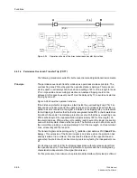
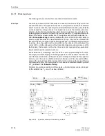
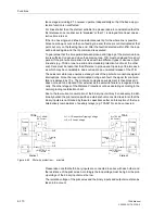
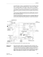
Figure 6-64
Pilot wire protection — principle
Please take note that both binary inputs are connected in series with each other and
the resistance of the pilot wires. Accordingly the loop voltage must be high or the pick-
up voltage of the binary inputs must be low.
The isolation voltage of the pilot wires and the binary inputs and outputs must also be
taken into account.
7SA6
Z1B
T1B
Direc
.
&
&
Q
S
R
Station 1
L+1
„>DisTel Rec.Ch1“
L–active
7SA6
Z1B
T1B
Direc
.
&
&
Q
S
R
L–2
L+1
„>DisTel Rec.Ch1“
L–active
Tripping
Tripping
Station 2
L+2
L+1, L–1 Respective Tripping Voltage
L+2, L–2 Loop Voltage
Pickup
Pickup
„Dis.T.SEND“
NC Contact
„Dis.T.SEND“
NC Contact
Summary of Contents for siprotec 7SA6
Page 2: ...Siemens Aktiengesellschaft Book No C53000 G1176 C156 2 ...
Page 18: ...xviii 7SA6 Manual C53000 G1176 C156 2 ...
Page 32: ...Introduction 1 14 7SA6 Manual C53000 G1176 C156 2 ...
Page 82: ...Hardware and Connections 2 50 7SA6 Manual C53000 G1176 C156 2 ...
Page 119: ...SIPROTEC 4 Devices 4 25 7SA6 Manual C53000 G1176 C156 2 Figure 4 20 CFC Logic example ...
Page 190: ...Configuration 5 62 7SA6 Manual C53000 G1176 C156 2 ...
Page 652: ...Installation and Commissioning 8 78 7SA6 Manual C53000 G1176 C156 2 ...
Page 724: ...Technical Data 10 56 7SA6 Manual C53000 G1176 C156 ...
Page 800: ...Appendix A 76 7SA6 Manual C53000 G1176 C156 2 ...
Page 866: ...Appendix B 66 7SA6 Manual C53000 G1176 C156 2 ...

