Introduction
1-3
7SA6 Manual
C53000-G1176-C156-2
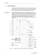
A voltage measuring input is provided for each phase–earth voltage. A further voltage
input (U
4
) may optionally be used to measure either the displacement voltage (e–n–
voltage) or any other voltage U
X
(for overvoltage protection). The analogue signals are
then routed to the input amplifier group IA.
The input amplifier group IA ensures that there is high impedance termination for the
measured signals and contains filters which are optimized in terms of band-width and
speed with regard to the signal processing.
The analogue/digital converter group AD has an analogue/digital converter and
memory modules for the data transfer to the microcomputer.
Microcomputer
System
Apart from processing the measured values, the microcomputer system also executes
the actual protection and control functions. In particular, the following are included:
−
Filtering and conditioning of the measured signals,
−
Continuous supervision of the measured signals,
−
Monitoring of the individual protection function pick-up conditions,
−
Interrogation of threshold values and time sequences,
−
Processing of signals for the logic functions,
−
Reaching trip and close command decisions,
−
Storage of fault annunciations, fault annunciations as well as fault recording data,
for system fault analysis,
−
Operating system and related function management such as e.g. data storage, real
time clock, communication, interfaces etc.
Informations are provided via output amplifier group OA.
Binary Inputs and
Outputs
The microcomputer system obtains external information through binary inputs such as
remote resetting or blocking commands for protective elements. The “µC” issues
information to external equipment via the output contacts. These outputs include, in
particular, trip commands to circuit breakers and signals for remote annunciation of
important events and conditions.
Front Elements
Light-emitting diodes (LEDs) and a display screen (LCD) on the front panel provide
information on measured values, events, states and finally the functional status of the
device.
Integrated control and numeric keys in conjunction with the LCD facilitate local
interaction with the 7SA6. All information of the device can be accessed using the
integrated control and numeric keys. The information includes protective and control
settings, operating and fault messages, and measured values (see also Chapter 7).
The settings can be modified as are discussed in Chapter 6.
If the device is provided with the main functions of system control, the required
operation can also be carried out via the front cover.
Serial Interfaces
A serial operating interface on the front panel is provided for local communications
with the 7SA6 through a personal computer. Convenient operation of all functions of
the device is possible using the SIPROTEC
®
4 operating program DIGSI
®
4.
A separate serial service interface is provided for remote communications via a
modem, or local communications via a substation master computer that is
permanently connected to the 7SA6. DIGSI
®
4 is required.
All 7SA6 data can be transferred to a central master or main control system through
the serial system interface. Various protocols and physical arrangements are
available for this interface to suit the particular application.
Summary of Contents for siprotec 7SA6
Page 2: ...Siemens Aktiengesellschaft Book No C53000 G1176 C156 2 ...
Page 18: ...xviii 7SA6 Manual C53000 G1176 C156 2 ...
Page 32: ...Introduction 1 14 7SA6 Manual C53000 G1176 C156 2 ...
Page 82: ...Hardware and Connections 2 50 7SA6 Manual C53000 G1176 C156 2 ...
Page 119: ...SIPROTEC 4 Devices 4 25 7SA6 Manual C53000 G1176 C156 2 Figure 4 20 CFC Logic example ...
Page 190: ...Configuration 5 62 7SA6 Manual C53000 G1176 C156 2 ...
Page 652: ...Installation and Commissioning 8 78 7SA6 Manual C53000 G1176 C156 2 ...
Page 724: ...Technical Data 10 56 7SA6 Manual C53000 G1176 C156 ...
Page 800: ...Appendix A 76 7SA6 Manual C53000 G1176 C156 2 ...
Page 866: ...Appendix B 66 7SA6 Manual C53000 G1176 C156 2 ...


