Installation and Commissioning
8-45
7SA6 Manual
C53000-G1176-C156-2
8.2.3
Checking Power Plant Connections
Before the device is energized for the first time, the device should be in the final operating environment for at least 2 hours to equalize the temperature and to minimize humidity and avoid condensation. Connection are checked with the device at its final location. The plant must first be switched off and grounded.
o
Protective switches (e.g. test switches, fuses, or miniature circuit breakers) for the
power supply and the measured voltages must be opened.
o
Check the continuity of all current and voltage transformer connections against the
system and connection diagrams:
G
Are the current transformers grounded properly?
G
Are the polarities of the current transformers the same?
G
Is the phase relationship of the current transformers correct?
G
Are the voltage transformers grounded properly?
G
Are the polarities of the voltage transformers correct?
G
Is the phase relationship of the voltage transformers correct?
G
Is the polarity for current input I
4
correct (if used), also refer to Subsection 8.1.2,
“Currents”?
G
Is the polarity for voltage input U
4
correct (if used, e.g. with broken delta winding or
busbar voltage), cf. also Subsection 8.1.2, “Voltages”?
o
Check the functions of all test switches that may be installed for the purposes of sec-
ondary testing and isolation of the device. Of particular importance are test switches
in current transformer circuits. Be sure these switches short-circuit the current trans-
formers when they are in the test mode (open).
o
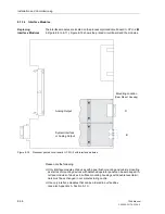
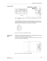
The short-circuit feature of the current circuits of the device are to be checked. An
ohmmeter or other test equipment for checking continuity is needed. Be sure that con-
tinuity is not simulated by the reverse connected current transformers themselves or
their short-circuit links.
G
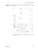
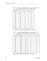
Remove the front panel of the device (see Figure 8-9 to 8-11).
G
Remove the ribbon cable connected to the I/O–2 board with the measured current
and measured voltage inputs (on the front side it is the right printed circuit board,
for housing size
1
/
3
, see Figure 8-9 [slot 19], for housing size
1
/
2
see Figure 8-10
[slot 33], for housing size
1
/
1
see Figure 8-11 [slot 33 right]. Furthermore, remove
the printed circuit board so that there is no more contact anymore with the plug-in
terminal.
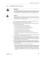
Warning!
Some of the following test steps will be carried out in presence of hazardous voltages.
They shall be performed only by qualified personnel which is thoroughly familiar with
all safety regulations and precautionary measures and pay due attention to them.
Caution!
Operating the device on a battery charger without a connected battery can lead to un-
usually high voltages and consequently, the destruction of the device. For limit values
see Subsection 10.2.1 under Technical Data.
Summary of Contents for siprotec 7SA6
Page 2: ...Siemens Aktiengesellschaft Book No C53000 G1176 C156 2 ...
Page 18: ...xviii 7SA6 Manual C53000 G1176 C156 2 ...
Page 32: ...Introduction 1 14 7SA6 Manual C53000 G1176 C156 2 ...
Page 82: ...Hardware and Connections 2 50 7SA6 Manual C53000 G1176 C156 2 ...
Page 119: ...SIPROTEC 4 Devices 4 25 7SA6 Manual C53000 G1176 C156 2 Figure 4 20 CFC Logic example ...
Page 190: ...Configuration 5 62 7SA6 Manual C53000 G1176 C156 2 ...
Page 652: ...Installation and Commissioning 8 78 7SA6 Manual C53000 G1176 C156 2 ...
Page 724: ...Technical Data 10 56 7SA6 Manual C53000 G1176 C156 ...
Page 800: ...Appendix A 76 7SA6 Manual C53000 G1176 C156 2 ...
Page 866: ...Appendix B 66 7SA6 Manual C53000 G1176 C156 2 ...

