xv
7SA6 Manual
C53000-G1176-C156-2
8
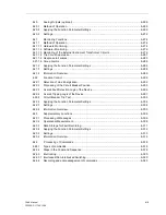
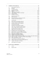
Installation and Commissioning ..................................................................................................... 8-1
8.1
Mounting and Connections.................................................................................................. 8-2
8.1.1
Installation ........................................................................................................................... 8-2
8.1.2
Termination variants ............................................................................................................ 8-9
8.1.3
Hardware Modifications ..................................................................................................... 8-15
8.1.3.1
General.............................................................................................................................. 8-15
8.1.3.2
Disassembly of the Device ................................................................................................ 8-16
8.1.3.3
Jumper Settings on Printed Circuit Boards........................................................................ 8-21
8.1.3.4
Interface Modules .............................................................................................................. 8-36
8.1.3.5
Reassembly of Device....................................................................................................... 8-40
8.2
Checking the Connections................................................................................................. 8-41
8.2.1
Data Connections .............................................................................................................. 8-41
8.2.2
Checking the Protection Data Communication.................................................................. 8-44
8.2.3
Checking Power Plant Connections .................................................................................. 8-45
8.3
Commissioning .................................................................................................................. 8-47
8.3.1
Testing mode and transmission blocking .......................................................................... 8-48
8.3.2
Checking the System (SCADA) Interface.......................................................................... 8-48
8.3.3
Checking the Binary Inputs and Outputs ........................................................................... 8-50
8.3.4
Checking Analog Outputs.................................................................................................. 8-52
8.3.5
Checking the Communication Topology............................................................................ 8-53
8.3.6
Tests for the Circuit Breaker Failure Protection................................................................. 8-56
8.3.7
Current, Voltage, and Phase Rotation Checks.................................................................. 8-59
8.3.8
Directional Checks with Load Current ............................................................................... 8-60
8.3.9
Polarity check for the voltage input U
4
.............................................................................. 8-61
8.3.10
Earth Fault Check in a Non-earthed System ..................................................................... 8-63
8.3.11
Polarity Check for the Current Measuring Input I
4
............................................................. 8-64
8.3.12
Measuring the operating time of the circuit breaker .......................................................... 8-68
8.3.13
Testing of the Teleprotection System ................................................................................ 8-69
8.3.13.1 Teleprotection with Distance Protection ............................................................................ 8-69
8.3.13.2 Teleprotection with Earth Fault Protection......................................................................... 8-72
8.3.13.3 Transfer Trip Signal Transmission for Breaker Failure Protection and/or Stub Protection 8-74
8.3.13.4 Signal Transmission for Intertripping and Direct Transfer Tripping ................................... 8-74
8.3.14
Testing User-Defined Functions ........................................................................................ 8-74
8.3.15
Trip and Close Test with the Circuit Breaker ..................................................................... 8-75
8.3.16
Switching Check for the Configured Operating Devices.................................................... 8-75
8.3.17
Triggering Oscillographic Recordings................................................................................ 8-75
8.4
Final Preparation of the Device ......................................................................................... 8-77
9
Routine Checks and Maintenance .................................................................................................. 9-1
9.1
General................................................................................................................................ 9-2
9.2
Routine Checks ................................................................................................................... 9-3
Summary of Contents for siprotec 7SA6
Page 2: ...Siemens Aktiengesellschaft Book No C53000 G1176 C156 2 ...
Page 18: ...xviii 7SA6 Manual C53000 G1176 C156 2 ...
Page 32: ...Introduction 1 14 7SA6 Manual C53000 G1176 C156 2 ...
Page 82: ...Hardware and Connections 2 50 7SA6 Manual C53000 G1176 C156 2 ...
Page 119: ...SIPROTEC 4 Devices 4 25 7SA6 Manual C53000 G1176 C156 2 Figure 4 20 CFC Logic example ...
Page 190: ...Configuration 5 62 7SA6 Manual C53000 G1176 C156 2 ...
Page 652: ...Installation and Commissioning 8 78 7SA6 Manual C53000 G1176 C156 2 ...
Page 724: ...Technical Data 10 56 7SA6 Manual C53000 G1176 C156 ...
Page 800: ...Appendix A 76 7SA6 Manual C53000 G1176 C156 2 ...
Page 866: ...Appendix B 66 7SA6 Manual C53000 G1176 C156 2 ...


