Functions
6-173
7SA6 Manual
C53000-G1176-C156-2
Inverse Time
Overcurrent Stages
IP, 3I0P with
ANSI
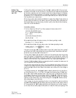
In the case of the inverse time overcurrent stages, various characteristics can be se-
lected, depending on the version of the device and the configuration (Section 5.1, ad-
dress
126
). For the ANSI–curves (address
126
Back-Up O/C
=
TOC ANSI
) the fol-
lowing are available in address
2661
ANSI Curve
:
Inverse
,
Short inverse
,
Long inverse
,
Moderately inv.
,
Very inverse
,
Extremely inv.
, and
Definite inv.
The curves and equations that the curves are based on, are shown in the technical
data (Section 10.5, Figure 10-2 to 10-3).
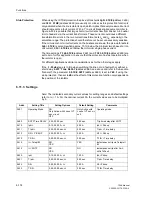
For the setting of the current thresholds
Ip>
(address
2640
) and
3I0p PICKUP
(ad-
dress
2650
) the same considerations as for the overcurrent stages of the definite time
protection (see above) apply. In this case it must be noted that a safety margin be-
tween the pick-up threshold and the set value has already been incorporated. Pick-up
only occurs at a current which is approximately 10 % above the set value.
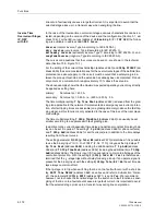
The above example shows that the maximum expected operating current may directly
be applied as setting here.
primary:
Set value Ip> = 630 A,
secondary: Set value Ip> = 5.25 A, i.e. (630 A / 600 A) · 5 A.
The time multiplier setting
Time Dial TD Ip
(address
2643
) is derived from the
grading coordination plan applicable to the network. If implemented as emergency
overcurrent protection, shorter tripping times are advisable (one grading time margin
above the fast tripping stage), as this function is only activated in the case of the loss
of the local measured voltage.
The time multiplier setting
TimeDial TD3I0p
(address
2653
) can usually be set
smaller according to a separate earth fault grading plan.
In addition to the current dependant time delay an additional constant time length de-
lay can be set if required. The setting
T Ip Add
(address
2646
for phase currents)
and
T 3I0p Add
(address
2656
for earth currents) are in addition to the time delays
resulting from the set curves.
The setting parameter
I(3I0)p Tele/BI
(address
2670
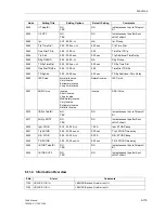
) determines if it is possible
to use the binary input “
>O/C InstTRIP
” (F.No.
7110
) to bypass the trip delays
Time
Dial TD Ip
(address
2643
) including the additional time
T Ip Add
(address
2646
)
and
TimeDial TD3I0p
(address
2653
) including the additional time
T 3I0p Add
(address
2656
). The binary input (if it is assigned) is common to all stages of the over-
current protection. With the setting
I(3I0)p Tele/BI
=
Yes
it is therefore deter-
mined that the I
P
–stage trips without delay following pick-up if an operate signal is
present at the binary input; with the setting
I(3I0)p Tele/BI
=
No
the set time de-
lays always come into effect.
If the Ip-stage is to retrip when switching the line on to a fault with or without a short
delay,
SOTF Time DELAY
(address
2680
, see above and refer to Sub-section “Gen-
eral”), the parameter
I> SOTF
(address
2625
) is set to Yes. We recommend, how-
ever, not to choose the sensitive stage for the switch on to a fault function as energiz-
ing of the line on to a fault should cause a large fault current. It is important to avoid
that the selected stage picks up in a transient way during line energization.
Summary of Contents for siprotec 7SA6
Page 2: ...Siemens Aktiengesellschaft Book No C53000 G1176 C156 2 ...
Page 18: ...xviii 7SA6 Manual C53000 G1176 C156 2 ...
Page 32: ...Introduction 1 14 7SA6 Manual C53000 G1176 C156 2 ...
Page 82: ...Hardware and Connections 2 50 7SA6 Manual C53000 G1176 C156 2 ...
Page 119: ...SIPROTEC 4 Devices 4 25 7SA6 Manual C53000 G1176 C156 2 Figure 4 20 CFC Logic example ...
Page 190: ...Configuration 5 62 7SA6 Manual C53000 G1176 C156 2 ...
Page 652: ...Installation and Commissioning 8 78 7SA6 Manual C53000 G1176 C156 2 ...
Page 724: ...Technical Data 10 56 7SA6 Manual C53000 G1176 C156 ...
Page 800: ...Appendix A 76 7SA6 Manual C53000 G1176 C156 2 ...
Page 866: ...Appendix B 66 7SA6 Manual C53000 G1176 C156 2 ...


