Configuration
5-30
7SA6 Manual
C53000-G1176-C156-2
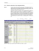
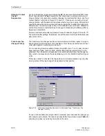
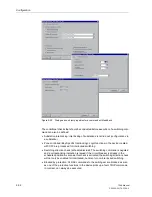
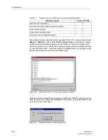
Figure 5-27
Selecting a function key as an information source — example
Configuring CFC as
a Source
If certain information should be created as a result of the implementation of a user de-
fined logic function (CFC), this information must appear in the matrix as a source from
CFC. Otherwise, this information will not be available to the user when editing the CFC
logic.
You must not configure information to CFC as a source if it is already configured to a
binary input.
Configuring Binary
Outputs as a
Destination
Up to thirty (30) information units (commands and indications) may be configured to
one output relay. One indication may be configured to up to ten (10) binary outputs
which include LEDs and output relays (cf. also margin header “Configuring a LED Dis-
play as a Destination” on page 5-33).
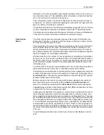
During configuration of binary outputs, you may select, for each output relay (besides
of the logic function itself), whether it should be latched (
L
) or unlatched (
U
). If you se-
lect latched, the output relay remains energized, even after the indication is no longer
present. It must be manually reset by pressing the “LED” Reset button on the front
panel of the device, or via a binary input with the indication function “
>LED Reset
”,
or via the serial system interface. If unlatched is selected, the output relay disengages
as soon as the indication disappears.
Fast Binary
Outputs
Some binary outputs of device 7SA6 - depending on the order variant, refer to “Gen-
eral Diagrams” in Section A.2 of Appendix A - have a response time which is approx.
3 ms shorter. Therefore they are very suited for sending trip commands as well as for
issuing initiate signals to signal transmission equipment for teleprotection.
High-speed
outputs
Depending on the device version (7SA6*1*–*M/N/P***–, 7SA6*2*–*M/N/P/Q/R/S***–)
the five binary outputs BA9, BA13, BA14, BA15 and BA16 are equipped with static
circuits with a response time of less than 1 ms. In these versions the outputs are used
preferably for issuing tripping commands. In the General Diagrams in Appendix A.2
they are designated with „high-speed”.
Binary Outputs for
Switching Devices
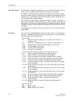
Take care when configuring binary outputs for switching devices. For switching de-
vices, the type of command (e.g., single or double commands, with or without feed-
back) is defined and configured to the output relay. If the preset command types are
not desired, then appropriate command types can be selected from the Information
catalog (see also “Entering Your Own Information” in the previous sub-section) and
inserted into the configuration matrix.
Summary of Contents for siprotec 7SA6
Page 2: ...Siemens Aktiengesellschaft Book No C53000 G1176 C156 2 ...
Page 18: ...xviii 7SA6 Manual C53000 G1176 C156 2 ...
Page 32: ...Introduction 1 14 7SA6 Manual C53000 G1176 C156 2 ...
Page 82: ...Hardware and Connections 2 50 7SA6 Manual C53000 G1176 C156 2 ...
Page 119: ...SIPROTEC 4 Devices 4 25 7SA6 Manual C53000 G1176 C156 2 Figure 4 20 CFC Logic example ...
Page 190: ...Configuration 5 62 7SA6 Manual C53000 G1176 C156 2 ...
Page 652: ...Installation and Commissioning 8 78 7SA6 Manual C53000 G1176 C156 2 ...
Page 724: ...Technical Data 10 56 7SA6 Manual C53000 G1176 C156 ...
Page 800: ...Appendix A 76 7SA6 Manual C53000 G1176 C156 2 ...
Page 866: ...Appendix B 66 7SA6 Manual C53000 G1176 C156 2 ...

