Functions
6-170
7SA6 Manual
C53000-G1176-C156-2
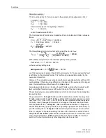
Calculation example:
110 kV overhead line 150 mm
2
as used in the example in Subsubsection 6.2.4.2:
s (length) = 60 km
R
1
/s
= 0,19
Ω
/km
X
1
/s
= 0,42
Ω
/km
Short circuit power at the beginning of the line:
S
k
'
= 2,5 GVA
current transformers600 A/5 A
The line impedance Z
L
and source impedance Z
S
are calculated with these values as
follows:
Z
1
/s =
√
0.19
2
+ 0.42
2
Ω
/km = 0.46
Ω
/km
Z
L
= 0.46
Ω
/km · 60 km
= 27.66
Ω
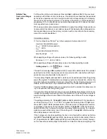
The three phase short circuit current at the end of the line is
I
F end
:
With a safety margin of 10 % the resultant primary setting value is:
Set value I>> = 1.1 · 2150 A = 2365 A
or the secondary setting value:
i.e. if the fault current is greater than 2365 A (primary) or 19.7 A (secondary) the fault
is definitely on the protected feeder. This fault may be cleared immediately by the
overcurrent protection.
Comment
: The calculation was carried out with scalar quantities which is sufficient for
overhead lines. If there is a large difference in the angle of the source and line imped-
ance, the calculation must be done with complex values.
An analogous calculation can be done for earth faults, whereby the maximum earth
fault current that flows during an earth fault at the end of the line is decisive.
The set time delays are pure additional delays, which do not include the operating time
(measuring time).
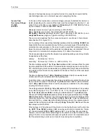
The parameter
I>> Telep/BI
(address
2614
) determines whether the delay times
T Iph>>
(address
2611
) and
T 3I0>>
(address
2613
) may be bypassed via the bi-
nary input “
>O/C InstTRIP
” (F.No.
7110
) or via the automatic reclose ready state.
The binary input (if assigned) is common to all stages of the overcurrent protection.
With the parameter
I>> Telep/BI
=
Yes
it is determined that the I>>–stages trip
without delay following pick up if there is an operating signal present at the binary in-
put; if the setting is
I>> Telep/BI
=
No
the set delay times always come into effect.
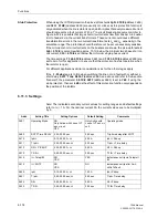
If the I>>-stage is to trip when switching the line on to a fault with or without a short
delay,
SOTF Time DELAY
(address
2680
, see above and refer to Sub-section “Gen-
eral”), the parameter
I>> SOTF
(address
2615
) must be set to Yes. For this fast
switch on to a fault protection any other stage may also be selected.
Z
S
110
2
kV
2
2500 MVA
------------------------------
4.84
Ω
=
=
I
F end
1.1 U
N
⋅
3
Z
S
(
Z
L
)
+
⋅
--------------------------------------
1.1 110 kV
⋅
3
4.84
Ω
(
27.66
Ω )
+
⋅
----------------------------------------------------------------
2150 A
=
=
=
Setting value I>>
1.1
=
2150 A
600 A
-------------------
5 A
⋅
⋅
19.7 A
=
Summary of Contents for siprotec 7SA6
Page 2: ...Siemens Aktiengesellschaft Book No C53000 G1176 C156 2 ...
Page 18: ...xviii 7SA6 Manual C53000 G1176 C156 2 ...
Page 32: ...Introduction 1 14 7SA6 Manual C53000 G1176 C156 2 ...
Page 82: ...Hardware and Connections 2 50 7SA6 Manual C53000 G1176 C156 2 ...
Page 119: ...SIPROTEC 4 Devices 4 25 7SA6 Manual C53000 G1176 C156 2 Figure 4 20 CFC Logic example ...
Page 190: ...Configuration 5 62 7SA6 Manual C53000 G1176 C156 2 ...
Page 652: ...Installation and Commissioning 8 78 7SA6 Manual C53000 G1176 C156 2 ...
Page 724: ...Technical Data 10 56 7SA6 Manual C53000 G1176 C156 ...
Page 800: ...Appendix A 76 7SA6 Manual C53000 G1176 C156 2 ...
Page 866: ...Appendix B 66 7SA6 Manual C53000 G1176 C156 2 ...

