Configuration
5-39
7SA6 Manual
C53000-G1176-C156-2
5.3
Creating User Defined Functions with CFC
General
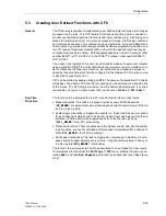
The 7SA6 relay is capable of implementing user defined logic functions which may be
processed by the relay. This CFC feature (Continuous Function Chart) is needed to
process user defined supervision functions and logic conditions (e.g. interlocking con-
ditions for switching devices) or to process measured values. Interlocking conditions
and command sequences, for example, may be programmed, using pre-defined func-
tion modules, by persons without any specialized software programming abilities. A to-
tal of 21 types of functional modules (FM), with which the desired functions may be
composed, are saved in a library. Detailed explanations are in the CFC manual, order
number E50417–H1176–C098, or in the DIGSI
®
4 manual, order number E50417–
H1176–C097.
The creation of a logical PLC function is performed by means of a personal computer
using application DIGSI
®
4 and transferred via the operator or service interface. In or-
der to create user defined logic functions, the indications and measured values re-
quired by these functions must first be configured in the matrix with CFC as the source
or destination (see Section 5.2).
CFC can be started by double-clicking on
CFC
. The names of all available CFC charts
will appear. The desired CFC chart for processing can be selected via a double-click
of the mouse. The CFC program will start, and the chart will be displayed. If no chart
is available yet, you can create a new chart via the menu
Create
→
CFC–Chart
.
Run-Time
Properties
The functions to be implemented in CFC may be divided into four task levels:
•
Measured values: This task is processed cyclically every 600 milliseconds
(
MV_BEARB
= measurement value processing) and might become slower if the de-
vice is in pick-up state.
•
System logic: Operation is triggered by events (i.e. these functions are processed
for each change of state at one of its inputs). System logic has lower priority than a
protection function and will be suppressed as soon as the relay picks up
(
PLC1_BEARB
= slow PLC processing).
•
Protective functions: These functions have the highest priority, and, like the system
logic functions, are event-controlled and processed immediately after a change of
state (
PLC_BEARB
= fast PLC processing).
•
Switchgear Interlocking: This task is triggered by commands. In addition it is proc-
essed cyclically approximately every second. It might becomes slower if device is
in pick-up state (
SFS_BEARB
= interlocking).
The function to be implemented must be associated to one of these four task levels.
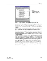
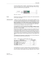
To implement a function from the
Settings
→
CFC
menu, activate the menu by se-
lecting
Edit
, and then
Run Sequence
, and then the desired task level (See Figure
5-34).
Summary of Contents for siprotec 7SA6
Page 2: ...Siemens Aktiengesellschaft Book No C53000 G1176 C156 2 ...
Page 18: ...xviii 7SA6 Manual C53000 G1176 C156 2 ...
Page 32: ...Introduction 1 14 7SA6 Manual C53000 G1176 C156 2 ...
Page 82: ...Hardware and Connections 2 50 7SA6 Manual C53000 G1176 C156 2 ...
Page 119: ...SIPROTEC 4 Devices 4 25 7SA6 Manual C53000 G1176 C156 2 Figure 4 20 CFC Logic example ...
Page 190: ...Configuration 5 62 7SA6 Manual C53000 G1176 C156 2 ...
Page 652: ...Installation and Commissioning 8 78 7SA6 Manual C53000 G1176 C156 2 ...
Page 724: ...Technical Data 10 56 7SA6 Manual C53000 G1176 C156 ...
Page 800: ...Appendix A 76 7SA6 Manual C53000 G1176 C156 2 ...
Page 866: ...Appendix B 66 7SA6 Manual C53000 G1176 C156 2 ...

