Appendix
A-13
7SA6 Manual
C53000-G1176-C156-2
A.2
General Diagrams
A.2.1
Panel Flush Mounting or Cubicle Mounting
7SA610
∗
–
∗
A/J
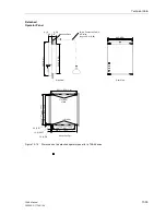
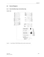
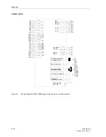
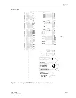
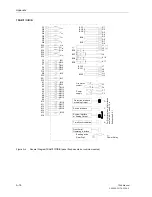
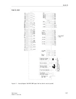
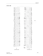
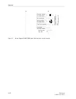
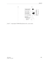
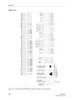
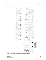
Figure A-1
General Diagram 7SA610
∗
−
∗
A/J (panel flush mounted or cubicle mounted)
Power
System Interface
or Analog Output
B
A
Earthing at the
supply
Rear Wall
R9
R10
BO7
F1
F2
( )
~
+
-
Live status
F3
F4
contact
1 2
3 2
Time Synchronisation
Q1
Q2
I
L1
Q3
Q4
I
L2
Q5
Q6
I
L3
R13
R14
U
4
R15
R17
U
L1
R18
U
L2
R16
U
L3
F5
F6
BI1
F8
F9
F10
F7
BI2
BI4
BI5
BI3
R3
R4
BO3
R6
BO4
R5
BO5
R2
BO2
R1
BO1
R7
R8
1 2
3 2
BO6
R11
R12
BO8
Sevice Interface
C
Protection Interface
D
Q7
Q8
I
4
F
o
r
P
in
A
lloc
a
ti
ons
of
In
te
rf
aces
see
T
abl
e
8
-11
and
8-12
in
Subs
ect
ion
8.
2.
1
Front Serial
Operating Interface
or Analog Output
Summary of Contents for siprotec 7SA6
Page 2: ...Siemens Aktiengesellschaft Book No C53000 G1176 C156 2 ...
Page 18: ...xviii 7SA6 Manual C53000 G1176 C156 2 ...
Page 32: ...Introduction 1 14 7SA6 Manual C53000 G1176 C156 2 ...
Page 82: ...Hardware and Connections 2 50 7SA6 Manual C53000 G1176 C156 2 ...
Page 119: ...SIPROTEC 4 Devices 4 25 7SA6 Manual C53000 G1176 C156 2 Figure 4 20 CFC Logic example ...
Page 190: ...Configuration 5 62 7SA6 Manual C53000 G1176 C156 2 ...
Page 652: ...Installation and Commissioning 8 78 7SA6 Manual C53000 G1176 C156 2 ...
Page 724: ...Technical Data 10 56 7SA6 Manual C53000 G1176 C156 ...
Page 800: ...Appendix A 76 7SA6 Manual C53000 G1176 C156 2 ...
Page 866: ...Appendix B 66 7SA6 Manual C53000 G1176 C156 2 ...

