Functions
6-196
7SA6 Manual
C53000-G1176-C156-2
a)
EV. FLT. MODE
blocks AR
:
The reclosure is blocked as soon as an sequential fault is detected. Tripping as a
result of the sequential fault is three-pole. This applies irrespective of whether three-
pole cycles are permitted or not. There are no further reclosure attempts; the auto-
matic reclosure function is blocked dynamically (see also above under subtitle “Re-
close Block”, page 191).
b)
EV. FLT. MODE
starts 3p AR
:
As soon as an sequential fault is detected the recloser switches over to a three-pole
cycle. All trip commands are now three-pole. The separately settable dead time for
sequential faults starts with the clearance of the sequential fault; after the dead time
the circuit-breaker receives a close command. The further sequence is the same as
for single and three-pole cycles.
The complete dead time in this case consists of the portion of the single-pole dead
time up to clearance of the sequential fault plus the dead time for the sequential
fault. This makes sense because the duration of the three-pole dead time is essen-
tial for the stability of the network.
If reclosure is blocked due to an sequential fault without the protection issuing a three-
pole trip command (e.g. for sequential fault detection with fault detection), the device
can send a three-pole trip command so that the circuit-breaker does not remain open
with one pole (Forced Three-pole Trip, see page 207).
Dead Line Check
(DLC)
If the voltage of a disconnected phase does not disappear following a trip, reclosure
can be prevented. A prerequisite for this function is that the voltage transformers are
connected on the line side of the circuit breaker. To select this function the dead line
check must be activated. The automatic reclosure function then checks the discon-
nected line for no-voltage: The line must have been without voltage for at least an ad-
equate measuring time during the dead time. If this was not the case the reclosure is
blocked dynamically.
This no-voltage check on the line is of advantage if a small generator (e.g. wind
generator) is connected along the line.
Reduced Dead
Time (RDT)
If automatic reclosure is performed in connection with time-graded protection, non-se-
lective tripping before reclosure is often unavoidable in order to achieve fast, simulta-
neous tripping at all line ends. The 7SA6 has a “reduced dead time (RDT)” procedure
which reduces the effect of the short-circuit on healthy line sections to a minimum. The
three phase voltages are measured for the reduced dead time. The voltage transform-
ers must be located on the line side of the circuit breaker.
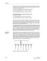
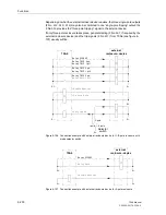
In the event of a fault close to on of the line ends, the surrounding lines can initially be
tripped because for example a distance protection detects the fault in its overreaching
zone Z1B (figure 6-103, relay location
III
). If the network is meshed and there is at
least one other infeed on the busbar B, the voltage there returns immediately after
clearance of the fault. For single-pole tripping it is sufficient if there is an earthed trans-
former with delta winding connected at busbar B which ensures symmetry of the volt-
ages and thus induces a return voltage in the open phase. This allows a distinction
between the faulty line and the unfaulted line to be made as follows:
Since line B–C is only tripped singled-ended at C, it receives a return voltage from the
end B which is not tripped so that at C the open phase(s) also has (have) voltage. If
the device detects this at position
III
, reclosure can take place immediately or in a
shorter time (to ensure sufficient voltage measuring time). The healthy line B–C is
then back in operation.
Summary of Contents for siprotec 7SA6
Page 2: ...Siemens Aktiengesellschaft Book No C53000 G1176 C156 2 ...
Page 18: ...xviii 7SA6 Manual C53000 G1176 C156 2 ...
Page 32: ...Introduction 1 14 7SA6 Manual C53000 G1176 C156 2 ...
Page 82: ...Hardware and Connections 2 50 7SA6 Manual C53000 G1176 C156 2 ...
Page 119: ...SIPROTEC 4 Devices 4 25 7SA6 Manual C53000 G1176 C156 2 Figure 4 20 CFC Logic example ...
Page 190: ...Configuration 5 62 7SA6 Manual C53000 G1176 C156 2 ...
Page 652: ...Installation and Commissioning 8 78 7SA6 Manual C53000 G1176 C156 2 ...
Page 724: ...Technical Data 10 56 7SA6 Manual C53000 G1176 C156 ...
Page 800: ...Appendix A 76 7SA6 Manual C53000 G1176 C156 2 ...
Page 866: ...Appendix B 66 7SA6 Manual C53000 G1176 C156 2 ...

